Page 31
CRIMP WITH PLIERS
ANC, THEN APPLY SOLDER
Figure 6
Check the connections just completed on the
socket and when you are sure no shorts exist,
snap the
cap over the socket
(if
in doubt,
tape connections).
It might be wise to put a
piece of tape on the outside of the shell with
the operating voltage of the cable plainly marked
for future reference.
) Refer to Figure 6 and at the 3" stripped
end of the cable install spade terminals
on the red and white leads. Connect both
the black lead and the shield pigtail to the
remaining spade terminal in similar man-
ner.
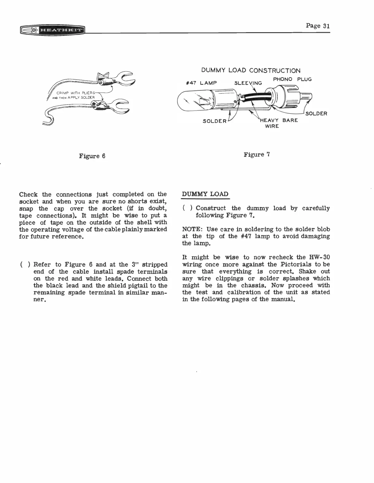
DUMMY LOAD CONSTRUCTION
#47 LAMP
DUMMY LOAD
SLEEVING
PHONO PLUG
WIRE
Figure 7
) Construct
the dummy load by carefully
following Figure 7.
NOTE: Use care in soldering to the solder blob
at the tip of the #47 lamp to avoid damaging
the lamp.
It might be wise to now recheck the HW-30
wiring once more against the Pictorials to be
sure that everything
is correct. Shake out
any wire clippings or solder splashes which
might be in the chassis. Now proceed with
the test and calibration of the unit as stated
in the following pages of the manual.