6 Electric Connection
KRONOS 20 35
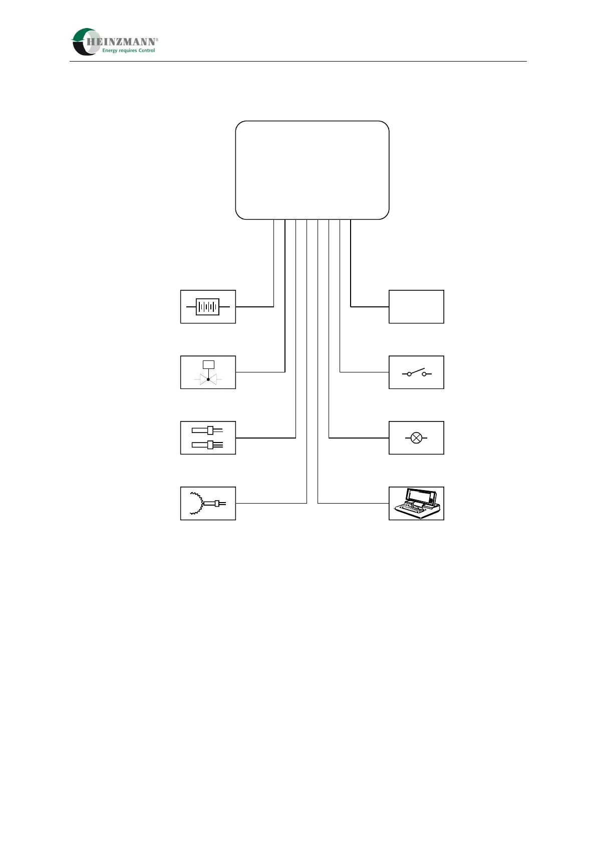
6.2 Cable Harness
W1
Battery
E-LES
Temperature- / Pressure Sensor
Magnetic Pickup
Closed Loop Input
Digital Inputs
Error Indicators
Communication
W2
W3
W4
W6
W7
W10
+
-
M
Control Unit
KRONOS 20
W5
Figure 19: Cable designations
W 1 power supply max. length 15 m 2 x 1.50 mm²
W 2 gas valve control max. length 15 m 4 x 0.75 mm²
W 3 pressure / temperature sensor max. length 15 m 4 x 0.75 mm²
W 4 speed pickup 2 x 0.75 mm²
W 5 actual power signal or λ-sensor signal max. length 15 m 2/4 x 0.75 mm²
W 6 motor stop switch 1 x 0.75 mm²
(the switch must be powered with +24V)
W 7 error message 1 x 0.75 mm²
(the switch must be powered with +24V)
W 10 communication max. 20 m
(at 9600 baud) 4 x 0.14 mm²