16
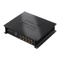
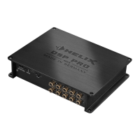
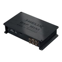
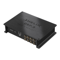
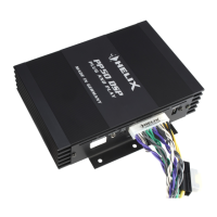
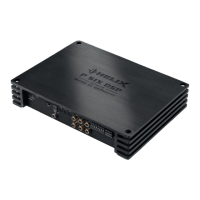
Connectors and control units
9
10
11 12
7
1 32 4 5 6
8
7
Ground lift switch
&DQ EH XVHG WR GH¿QH WKH FRQQHFWLRQ
between the grounding of the inputs and
outputs.
8
Control pushbutton
Use this button to either switch between the
setups or initiate a reset of the device.
9
Status LED
This LED indicates the operating mode of the
DSP and which setup has been chosen.
10
USB input
Connects the HELIX DSP PRO MK2 to your
PC.
11
Control Input
Multifunction interface for e.g. an optional
remote control or other HELIX accessory.
12
Line Output
/LQHRXWSXWVIRUFRQQHFWLQJDPSOL¿HUV0DNH
sure that the remote output is used to turn on
these devices.
1
Line Input
5&$ LQSXWV IRU FRQQHFWLQJ SUHDPSOL¿HU
signals.
2
Coax Input
Electrical input for digital stereo signals
(SPDIF format).
.
3
Optical Input
Optical input for digital stereo signals (SPDIF
format).
4
Clipping LED
This LED lights up red if one of the analog
inputs is overdriven.
5
Highlevel Input
Highlevel speaker inputs for connecting a
factory radio or an aftermarket radio without
pre-amp / line outputs.
6
Power Input
Connector for the DC power supply with an
additional remote in- and output. The remote
output has to be used to switch on external
DPSOL¿HUV