2 ‑ Maxima XTEND AX
PARTS AND CONTROLS
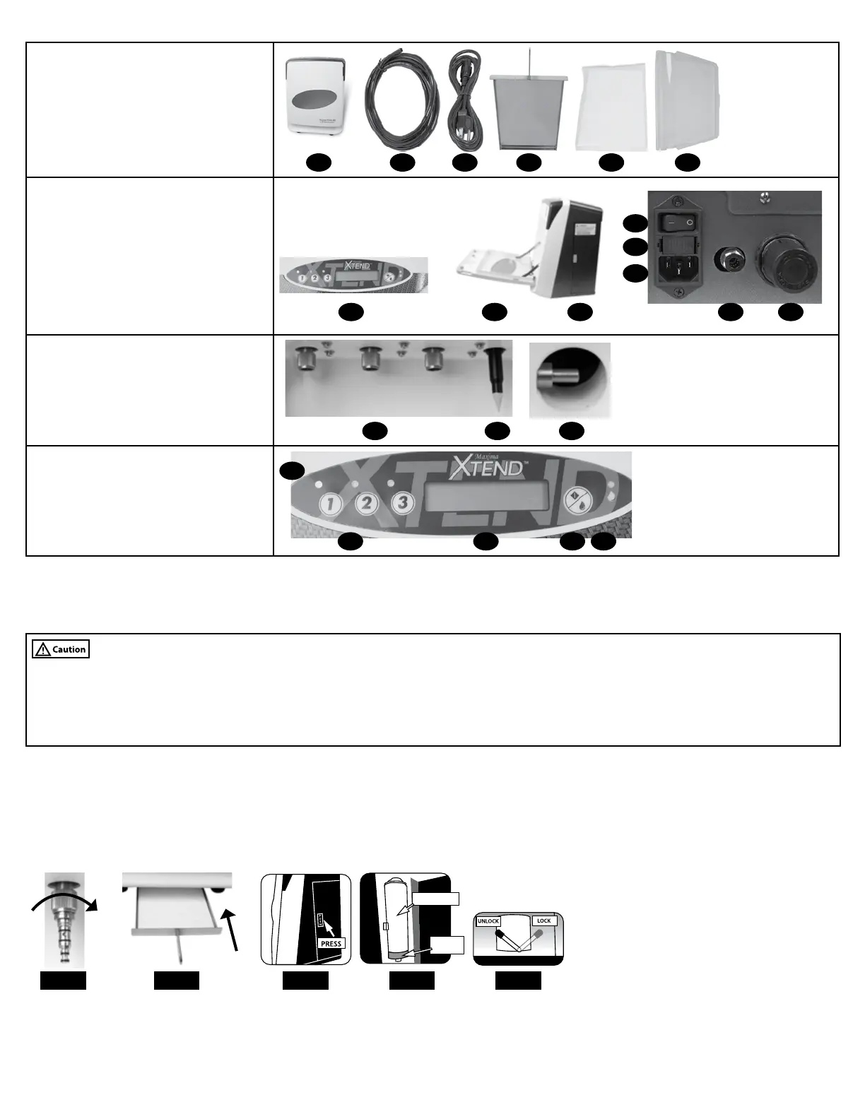
In the Box
1. Main Unit
2. Air Tube
3. Power Cord
4. Oil Tray
5. 3‑Pack Oil Tray Liners
6. Window Cover
1 2 3 4 5 6
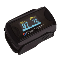
Main Unit - External
7. Control Panel
8. Front Door
9. Lubricant Door
10. Power Switch
11. Fuse Holder
12. Power Cord Connection
13. Air Connection
14. Air Regulator
10
7 8 9
11
12
13 14
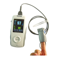
Main Unit - Internal
15. 4‑hole Connectors
16. Chuck Nozzle
17. Internal Oil Suction
15 1716
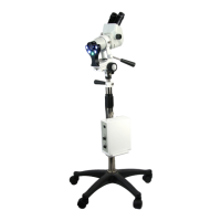
Control Panel
18. Handpiece Selector Lights
19. Handpiece Selector Buttons
20. LCD Display
21. Start Button
22. Empty Spray Can Warning Light
222120
18
19
ASSEMBLY SETUP
Note: Leave adequate space around the Maxima XTEND AX for all connections. The Maxima XTEND AX should be positioned on a rm, at,
vibration‑free surface.
• Air supply must be clean and oil free.
• Make sure the valve for main air supply is not opened until set up is complete.
• Oil may leak if spray can is not properly seated. If can is loose, adjust can holder by unscrewing or turning to the left.
• Use only Maxima XTEND AX spray. Using other cleaners may damage unit.
• Make sure 4‑hole connector nut is securely tightened when handpiece or service adapter is attached to avoid creating an air and/or oil leak.
1. Insert air tube completely into air connection on back of unit.
2. Connect other end of air tube to main air supply.
Note: Air Regulator dial is pre‑set to 4.5 bars. Recommended air pressure is 4.5 bars. Air pressure outside 4 ‑ 6 bars will result in an error code.
3. Connect one end of power cord to the power cord connection and plug other end into grounded electrical outlet.
4. If using service adapters, insert adapter into 4‑hole connector & tighten nut (Fig. 1).
FIG. 3FIG. 1
SPRAY CAN
STAND
FIG. 4
FIG. 5FIG. 2
5. Place 1 oil tray liner in oil tray and insert completely into lower front of unit (Fig. 2).
6. Press the “push” label on lubricant door to open (Fig. 3).
7. Move lever into unlocked position (Fig. 5), then place Maxima XTEND Spray (570‑0073) on stand (Fig. 4).
8. Ensure can nozzle is properly seated, then move lever into locked position (Fig. 5).
9. Open main air valve to pressurize maintenance unit.