3. UNIT SPECIFICATION
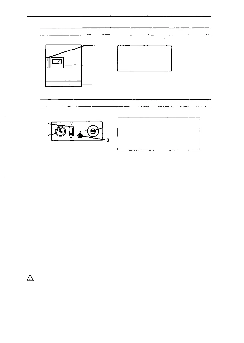
Fig. 1/3: Overview of the control elements
I 1 c
- -~ i—.
I 4-
— B
A
U LJ
A Switchgear unit
B Automatic control unit
C Door handle
Item A: Swltchgear unit
Fig.
1 -
4-
• 1
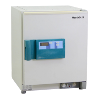
2/3: Switchgear unit control panel
ON / OFF switch:
-2
1 On / Off switch
2 Overtemperature protection,
control element
3 "Fault" signal lamp
4 Fresh-air flap adjustment
To switch the unit on and off:
"on" = Unit switched on, the temperature Inside the unit appears on the display panel
of the control unit,
"off' = Unit switched off, temperature display off.
• 2 & 3 Overtemperature protection device / signal lamp:
The unit is equipped with an electronic upper-limit cut-out device (TWB) of protection class 2
as defined by DIN 12 880 Part 1. II Is electrically and functionally independent of the temperature
control system. In the event of a fault In the unit heating system, the operational TWB shuts
down the unit heating across all poles as soon as the temperature exceeds the preset value.
The red signal lamp Indicates activation of the protection function (Fig. 2/3: Item 3).
The unit must be reset manually, by pressing the control element.
* Allow the unit to cool down (by approx. 30 *C), press the control element, the red signal lamp
will go out.
The operate value Is adjusted with the help of a tool (coin, screwdriver...).
Adjust (o the required protection level:
• to upper temperature limit» unit protection (protects the unit and its environment).
*• to approx. 10 *C higher than the operating temperature set on the control unit =
material protection (protects the unit, Its environment and the loaded material).
Ensure that the overtemperature protection device works properly by conducting a
functional check at regular Intervals, every 3 months at least, and check the electrical
equipment at least once a year.
10/34
50 042 750
Issue: May, 1994