36
1
3
2
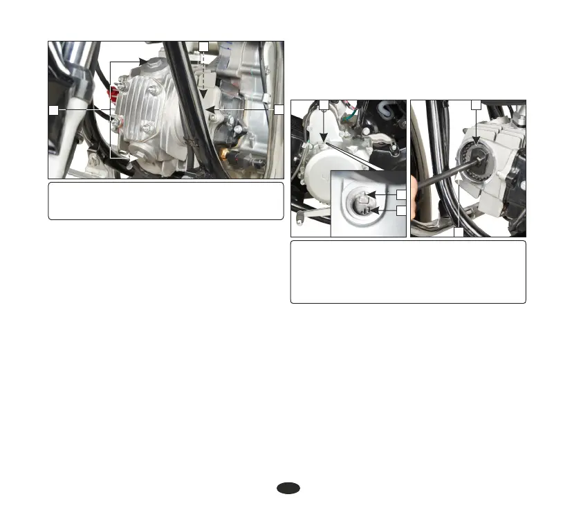
(1) Tappet covers
(2) Gasket
(3) Cylinder head left side cover
•
Remove the timing hole cap (4). Rotate the
cam sprocket (7) clockwise using the
special tool (8) until the ‘T’ mark (5) on the
flywheel coincides with the index mark (6)
on the left crankcase cover. In this position
the piston will either be on the compression
or exhaust stroke. The adjustment must be
made when the piston is at Top Dead
Center and both the inlet and exhaust valves
are closed. This condition can be
determined by moving the rocker arms. If
they are free, it is an indication that the
valves are closed and the piston is in
(4) Timing hole cap
(5) 'T' mark
(6) Index mark
(7) Cam sprocket
(8) Special tool
4
6
5
7
8
• Check the clearance by inserting the feeler
gauge (9) between the adjusting screw
(10) and valve stem (11).
Standard clearance
Intake: 0.10 mm
Exhaust: 0.10 mm
compression stroke. If they are tight, the
valves are open, rotate the cam sprocket
O
(7) 360 clockwise and re-align the 'T'
mark with the index mark.