Do you have a question about the Hettich EBA 20S and is the answer not in the manual?
Guidelines on authorized repairs, use of original parts, and liability for modifications.
Explanation of hazard area symbols and safety-relevant warnings in the document.
Lists the main electrical components like control panel, power board, motor, and sensors.
Details the control panel's tasks, input, and communication via TTL interface.
Describes the power board's role in voltage supply, motor control, and error evaluation.
Explanation of the three-phase motor and its speed monitoring via sensor.
Details the function of the brake resistor and the overtemperature fuse.
Describes the lid lock mechanism and the imbalance detection switch.
Covers checking fuses, supply voltage, and referencing error messages for diagnostics.
Step-by-step guide to reset the centrifuge using the mains switch.
Provides a brief description and page reference for each error code displayed.
In-depth explanation of error causes, consequences, and reset procedures for specific faults.
Instructions on how to set the correct machine version (EBA 20S) for the control panel.
Procedures to check the currently set machine version.
Procedures to check the currently set programme versions.
Steps to adjust the brake deceleration time for the centrifuge.
Details on the lid lock control and jumper setting on the power board.
How to adjust the imbalance switch sensitivity for safe operation.
Guide on how to safely replace the mains input fuses with correct ratings.
Procedures for performing functional and safety tests after repair.
Table listing components, their plugs, connections, and corresponding description sections.
Step-by-step instructions for replacing the motor, speed sensor, and bearings.
Guide for replacing the power board and control panel, noting heat conduction.
Procedures for replacing brake resistor, overtemp fuse, and flat ribbon cable.
Instructions for replacing the appliance plug, imbalance switch, and lid lock.
List of cable abbreviations and their corresponding colours used in the diagrams.
Detailed circuit diagram showing component connections and plug assignments.
Testing speed sensor signals and motor coil resistance/overtemp switch.
Testing brake resistor, overtemp fuse, and lid lock switch/solenoid.
Testing imbalance switch and measuring intermediate voltage on the power board.
Key technical data including model, voltage, capacity, speed, and ambient conditions.
Information on EMC, safety classifications, physical dimensions, and weight.
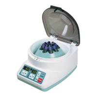
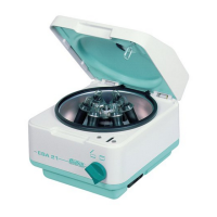
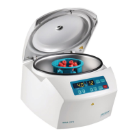
Illustrative diagram showing the physical layout and numbered components of the EBA 20S.
| Type | Benchtop centrifuge |
|---|---|
| Motor | Brushless DC motor |
| Temperature Range | Ambient |
| Timer Range | 1 to 99 minutes |
| Power Supply | 230 V / 50 Hz |