10 January 2019
Module description PLT-01628, Rev. D.2
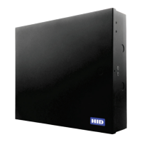
Physical features include:
႑ Console: For internal use.
႑ SD Card Socket: Insertion point for the SD Card with PAM Firmware.
႑ Power Connector: Connects the PAM to the power supply.
႑ Ground Connector: Connect the PAM to Earth ( ) using the lug built onto the PAM.
႑ Wiegand 1 and 2 Connector: Connects the PAM to the PACS.
႑ GP I/O: General Purpose I/O. Reserved for future use.
႑ Relay 1 and 2 (if equipped): Customer configurable for auxiliary purposes.
႑ Tamper Monitoring: Enables the system to monitor a normally closed or open (NC/NO) tamper line
wired to the case. This sends a log message back to Reader Services if the tamper line is activated.
Typically, this monitoring is done by the PACS.
႑ Power Failure Monitoring: Enables the system to monitor a normally closed or open (NC/NO) power
fail line. This sends a log message back to Reader Services if the power fail line is activated. Typically,
this monitoring is done by the PACS.
႑ DIP Switch: Configures the mode on which the PAM is running.
႑ Reader 1 and 2 Connector: Connects to the supported reader.
႑ Termination Resistor Jumpers: Located inboard from the Reader 2 Connector and includes RS-485
ports. Use when connecting Reader 1 and 2.
႑ Ethernet: Connects the PAM to the Network.
Note: If using a Rev A PAM (91000ANNNN or 91000ABNNN), some Gigabit Ethernet Switches may
require setting the port to 100 Mbps or 10 Mbps.
႑ RS-485: A serial port reserved for future use.
PIN Assignment
1
TMP
2
GND
PIN Assignment
1
PFL
2
GND
CAUTION
Do not use relays for access control, this voids UL certification.
WARNING
It is recommended to disable POE power on the port the PAM is connected to if the switch
is a POE switch.
If using a Rev A PAM (91000ANNNN or 91000ABNNN), the POE power must be turned off
to prevent damage to PAM or switch; or use a non-POE switch.