5. Servo operating
5-1
5.1 Basics of loader
You should install the servo motor and drive according to the installation condition. After
connect the power supply circuit and motor wiring. You should check the motor parameter (P01-
--). Use the loader to check that motor parameter is set to normal running condition. This
parameter show to you the basic information for the servo motor which is connected to the drive.
Then you must monitor the group indicating the motor status (StE--) to check whether various
commands and limits values are properly set. And if this is your first time operating the unit, you
must verify the stability through autotuning or test operation of Jog and Auto Jog. Autotuning
operation can be done online and you do not need to execute this operation when the gain of
stable control system is ensured offline.
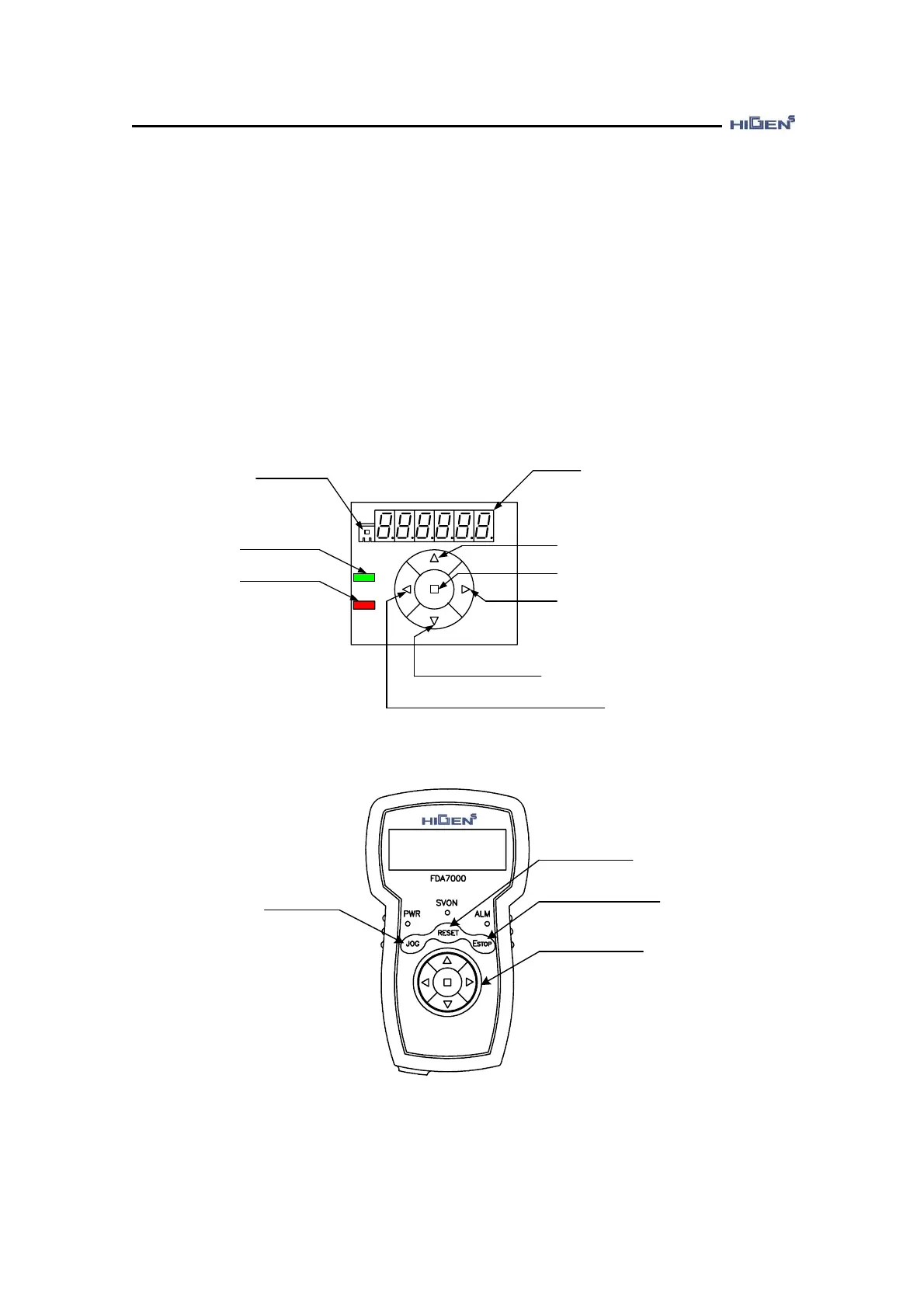
DISPLAY part
CN5 (Battery connection)
LED1_Green
(Charging)
LED1_Red
(Alarm condition)
UP Key
(Mode change, parameter value increase)
ENTER Key
(Parameter value change, confirmation)
RIGHT Key
(Move to right for parameter change and menu)
DOWN Key
(Mode change, parameter value decrease)
LEFT Key
(Move to left for parameter change and menu)
[ Overview diagram of internal mounter loader]
ALARM RESET
EMERGENCY STOP
KEY JOG ON
Same as mounter
loader function
HIGEN
[ Overview diagram of digital loader]