ID6000 Series Smart Code Reader User Manual
2
Table 1-1 Description
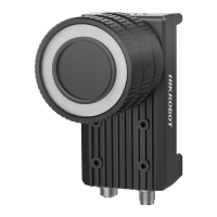
It refers to the device’s lens cap.
Note
The type II device does not have the lens cap.
It is used to fix the device to installation position. It is
recommended to use M4 screw.
Gigabit Ethernet
Interface
It refers to gigabit Ethernet interface for transmitting
data.
It provides power, input/output, and serial port signal.
The interface is designed with screw threads to tighten
connection between the device and cable, and thus
avoiding influence caused by vibration.
It is the power indicator. The indicator is solid blue when
the device operates normally.
It is network connection indicator. The indicator is solid
green when the network transmission is normal.
It is network transmission indicator. The indicator is
flashing yellow when the network transmission is
normal. The indicator flashing speed is related with data
transmission speed.
The device has 2 user-defined indicators, U1 and U2.
They are used to indicate whether some functions of the
device are normal or not.
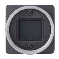
It is used to install the lens.
 Loading...