Video Intercom Door Station·User Manual
55
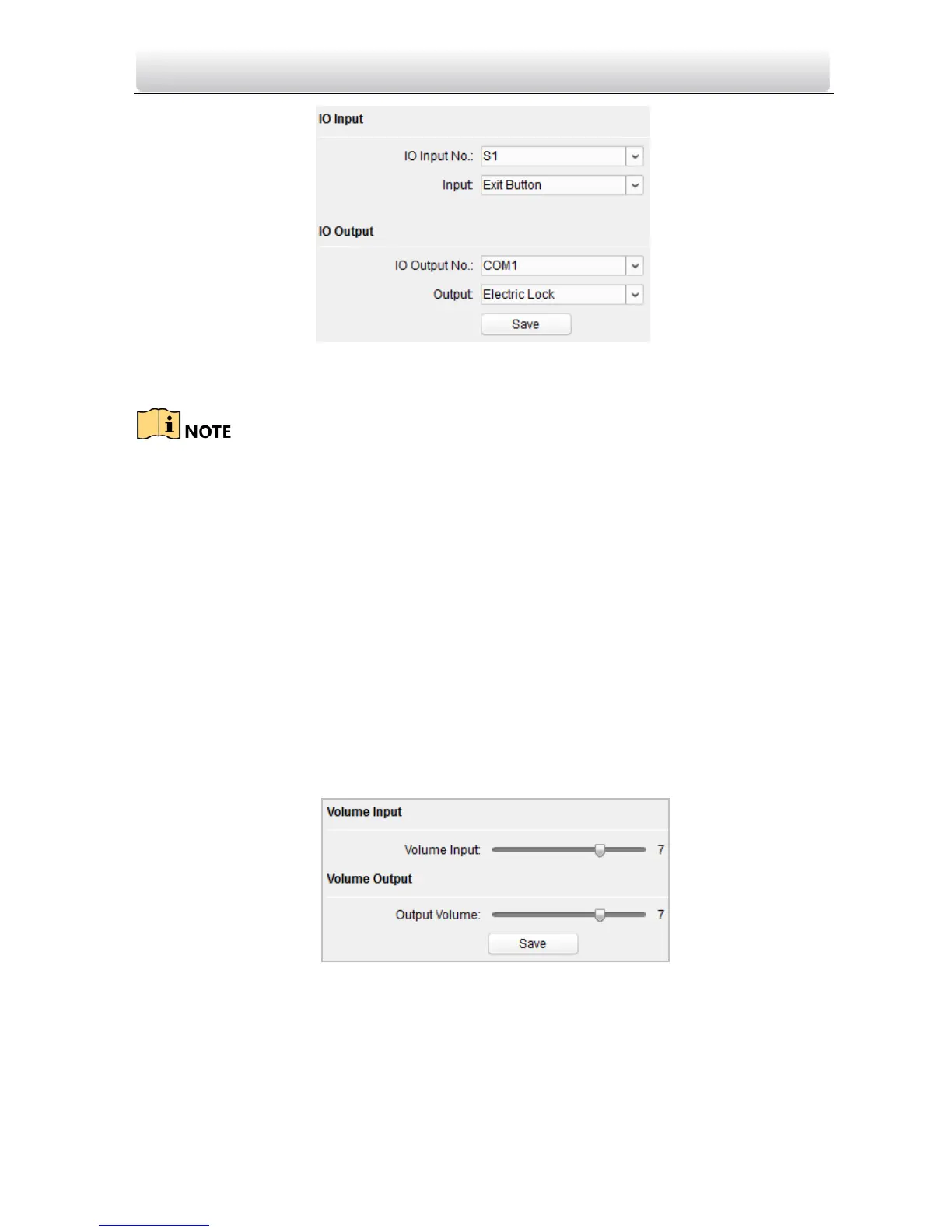
2. Select I/O input No., input mode, output No., and output mode.
3. Click Save to enable the settings.
For door station (D series), there are 8 I/O Input Terminals. Terminal 1~4 correspond
to SENSOR interfaces (S1, S2, S3, S4) of door station. Terminal 5~8 correspond to
interfaces of ALARM IN (A1, A2, A3, A4). You can select an I/O input No. (S1, S2, S3, S4,
AI, A2, A3, A4) from the drop-down list and set the I/O input as door magnetic exit
button.
For door station (V series), there are 4 I/O Input Terminals, corresponding to SENSOR
interfaces (S1, S2, S3, S4) of door station.
For door station (D series and V series), there are 4 I/O Output Terminals.
Terminal 1~2 correspond to DOOR interfaces (NO1/COM1/NC1; NO2/COM2/NC2) of
door station. You can enable/disable IO Out by selecting from the dropdown list.
Terminal 3~4 correspond to interfaces of ALARM OUT (AO1+, AO1-; AO2+, AO2-).
Volume Input and Output
Step:
1. Click Volume Input/Output to enter the volume input and output interface.
2. Slide the slider to adjust the volume input and volume output.
3. Click Save to enable the settings.
Deploy Info
In the Deploy Info interface, you can view which kind of device or client will receive the
alarm message and arm message from the door station.
 Loading...