User Manual of the DS-1004K keyboard
5
Chapter 2
Device Appearance
2.1 Rear Panel Description
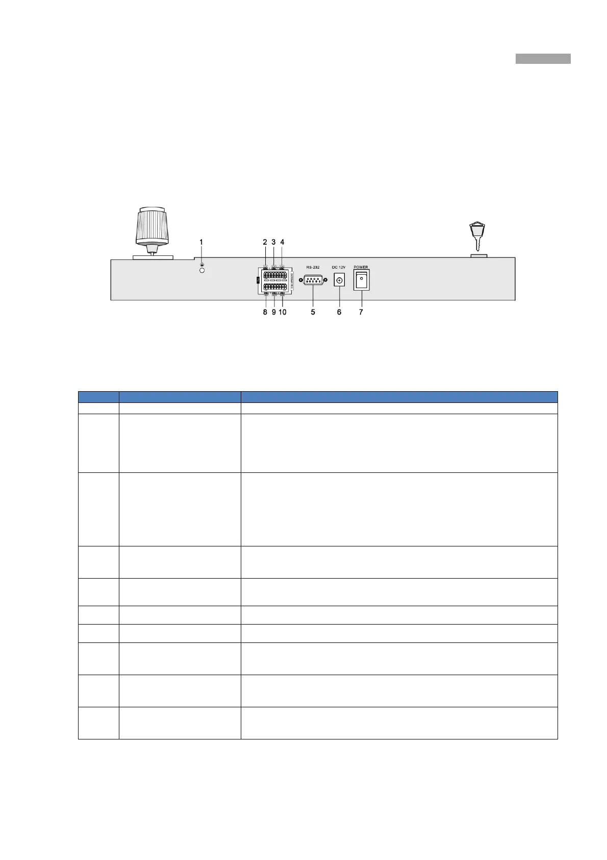
Figure 2-1 The Rear Panel of DS-1004KI Keyboard
Notes
:
The green end with a G identifier on the rear panel is for grounding.
Number Physical Interfaces Description
1
Grounding The pillar for grounding.
2
PTZ-CON
(PTZ Control Signal Output)
As main keyboard: Connect the dome camera or the RS485 of the PTZ: TA
connects to RS485+, and TB connects to RS485-.
As auxiliary keyboard: Connect the PTZ-AUX interface of the upper level
keyboard: TA connects to RA and TB connects to RB.
3
DVR/MATRIX-CON1
(DVR Control Signal Output)
As main keyboard: Connect the DVR KB interface; TA connects D+
,
TB
connects D-; When connecting the RS-485 of the VMS: TA connects to the 6
th
pin
and TB connects to 5
th
pin. When using the RS-485-to-RS-232 interface: TA
connects to 4
th
pin and TB connects to 3
rd
pin.
As auxiliary keyboard: Connect the AUX2 interface of the upper level keyboard.
TA connects to RA and TB connects to RB.
4
DVR/MATRIX-CON2
(Control Signal Output)
Output the RS-485 signal received by the 9
th
interface identified in the figure
above (AUX 1 interface).
5
RS232 Serial Interface
For the keyboard firmware upgrading and the control interface for the analog
matrix.
6
Power Supply 12VDC
7
Power Switch Power on/ off
8
PTZ-AUX
(Auxiliary keyboard PTZ
control signal input)
Connect to the lower level PTZ-CON interface; RA connects to TA and RB
connects to TB.
9
DVR/MATRIX-AUX1
(Auxiliary keyboard DVR
control signal input)
Connect a RS-485 signal source to receive the RS-485 signal.
10
DVR/MATRIX-AUX2
(Auxiliary keyboard control
signal input)
Connect to the DVR/MATRIX-CON interface of the lower level keyboard: RA
connects to TA, RB connects to TB.
We name the keyboard directly connecting the main keyboard upper level keyboard and we call the keyboard connecting to the upper
level keyboard the lower level keyboard. For detailed information, see Chapter 2.4 for typical wiring methods.

 Loading...