Installation Manual of Network Camera
10M/100M self-adaptive Ethernet interface
VIDEO OUT: Video output interface
AUDIO OUT: Audio output interface
POWER: Power LED indicator
MIC IN: Audio input interface
IN, G: Alarm input interface
1A, 1B: Alarm output interface
Notes:
To reset the default parameters to the camera, you need to press and hold the RESET
button and power on the camera. After the power on of the camera, you must still press and
hold the Reset button for about 20 seconds.
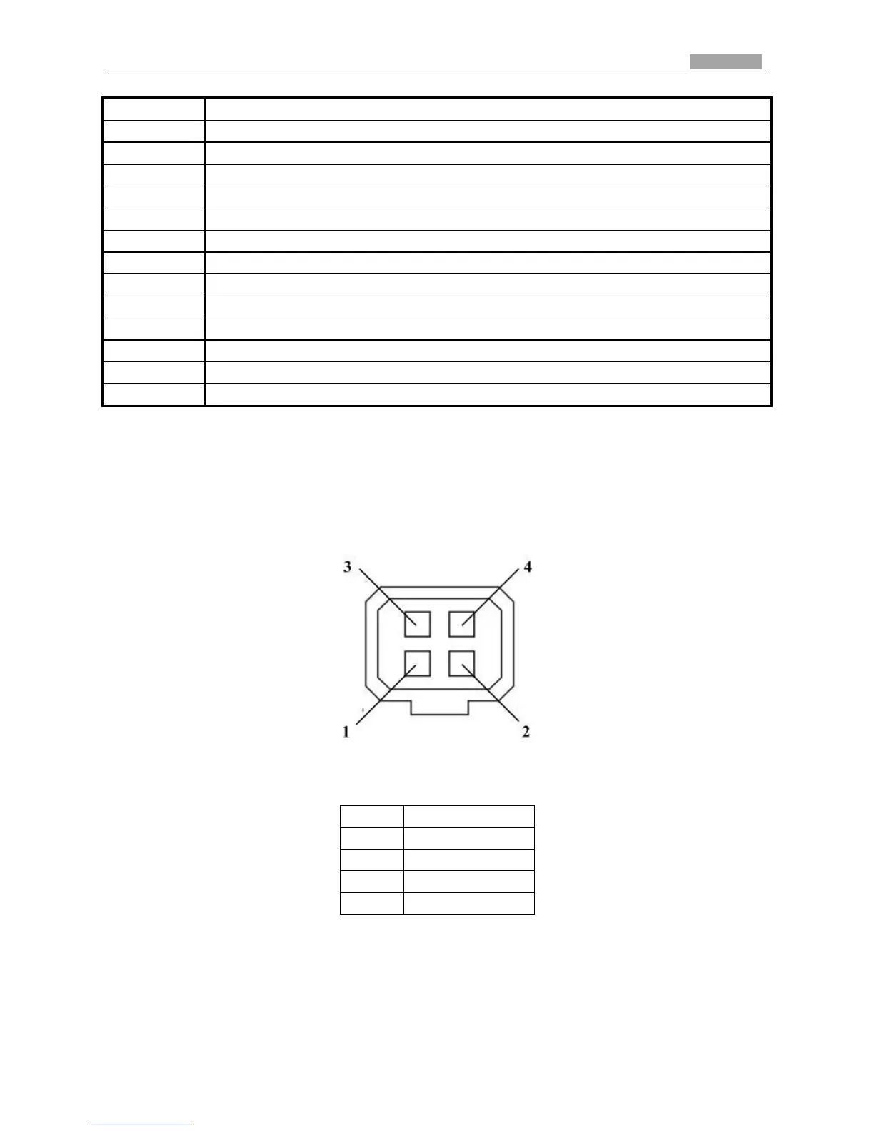
The type of auto-iris interface is shown in Figure 2-10, and the definition of each pin is
shown below:
Figure 2-10 Auto-iris Interface
Table 2-6 Pins
Damp+, Damp-, Drive+ and Drive- pins are used when the auto-iris is driven by DC.
Camera wiring Diagram: