Do you have a question about the Hill-Rom VersaCare P3200 and is the answer not in the manual?
Provides an overview of the service manual's purpose, audience, and organization.
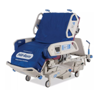
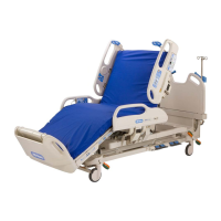
Details the physical and functional specifications of the VersaCare™ Bed.
Presents critical safety warnings and precautions for servicing the bed.
Procedures to verify the correct operation of various bed functions.
Troubleshooting procedures for specific bootloader and error conditions.
Troubleshooting lockout errors and CPR switch failures.
Procedures to diagnose and resolve unexpected hilow motor motion.
Troubleshooting unexpected motion for multiple bed motors.
Troubleshooting procedures to address motor overcurrent faults.
Troubleshooting issues where the hilow motor position rate is too high.
Troubleshooting issues where the hilow motor position rate is too low.
Procedures for diagnosing absolute minimum drive current failures.
Troubleshooting network heartbeat failures within the system.
Diagnosing logic board failures potentially caused by the patient pendant.
Procedures for troubleshooting logic circuit failures.
Troubleshooting procedures for nuisance trips of bed functions.
Steps to diagnose and resolve issues where bed motors do not operate.
Troubleshooting steps when the bed has no AC power.
Diagnosing issues when AC power is present but motors do not function.
Troubleshooting procedures for a lack of DC power to the bed.
Diagnosing and resolving issues with non-functional siderail controls.
Troubleshooting siderail detection issues without the SideCom system.
Troubleshooting siderail detection issues when using the SideCom system.
Troubleshooting steps for air surface problems, part 1.
Troubleshooting steps for air surface problems, part 2.
Diagnosing system errors that do not display a flash code.
Troubleshooting procedures for mattress disconnection errors.
Diagnosing and resolving head angle sensor errors.
Troubleshooting for head Force Sensing Resistor (FSR) issues.
Procedures for diagnosing and resolving accumulator pressure issues.
Troubleshooting steps for a missing 24V DC input.
Diagnosing issues where the head zone pressure is not reached.
Diagnosing issues where the seat zone pressure is not reached.
Diagnosing issues where the foot zone pressure is not reached.
Troubleshooting issues with the right turn assist pressure.
Troubleshooting issues with the left turn assist pressure.
Procedures for diagnosing and resolving scale error 0.
Procedures for diagnosing and resolving scale error 1.
Procedures for diagnosing and resolving scale error 2.
Procedures for diagnosing and resolving scale error 3.
Troubleshooting scale errors specific to European models.
Troubleshooting steps for the SideCom communication system.
Troubleshooting the patient position monitor system when used with a scale display.
Troubleshooting the patient position monitor system without a scale display.
Procedures for diagnosing and resolving CRC errors.
Troubleshooting issues related to the patient pendant.
Troubleshooting the obstacle detection system of the bed.
Troubleshooting procedures when the bed will not drive using IntelliDrive.
Diagnosing drive and wheel issues with IntelliDrive.
Troubleshooting issues where the IntelliDrive wheel will not stow.
Procedure for checking the battery status of the IntelliDrive system.
| Type | Hospital Bed |
|---|---|
| Trendelenburg Position | Yes |
| Reverse Trendelenburg Position | Yes |
| Side Rails | Yes, integrated |
| Power Source | Electric |
| Wheel Type | Locking casters |
| Height Adjustment | 15" - 30" |
| Maximum Head Elevation | 70 degrees |
| Maximum Knee Elevation | 40 degrees |
| Height Adjustability | 15" - 30" |
| Head and Foot Adjustment | Yes |
| Weight Capacity | 500 lbs |