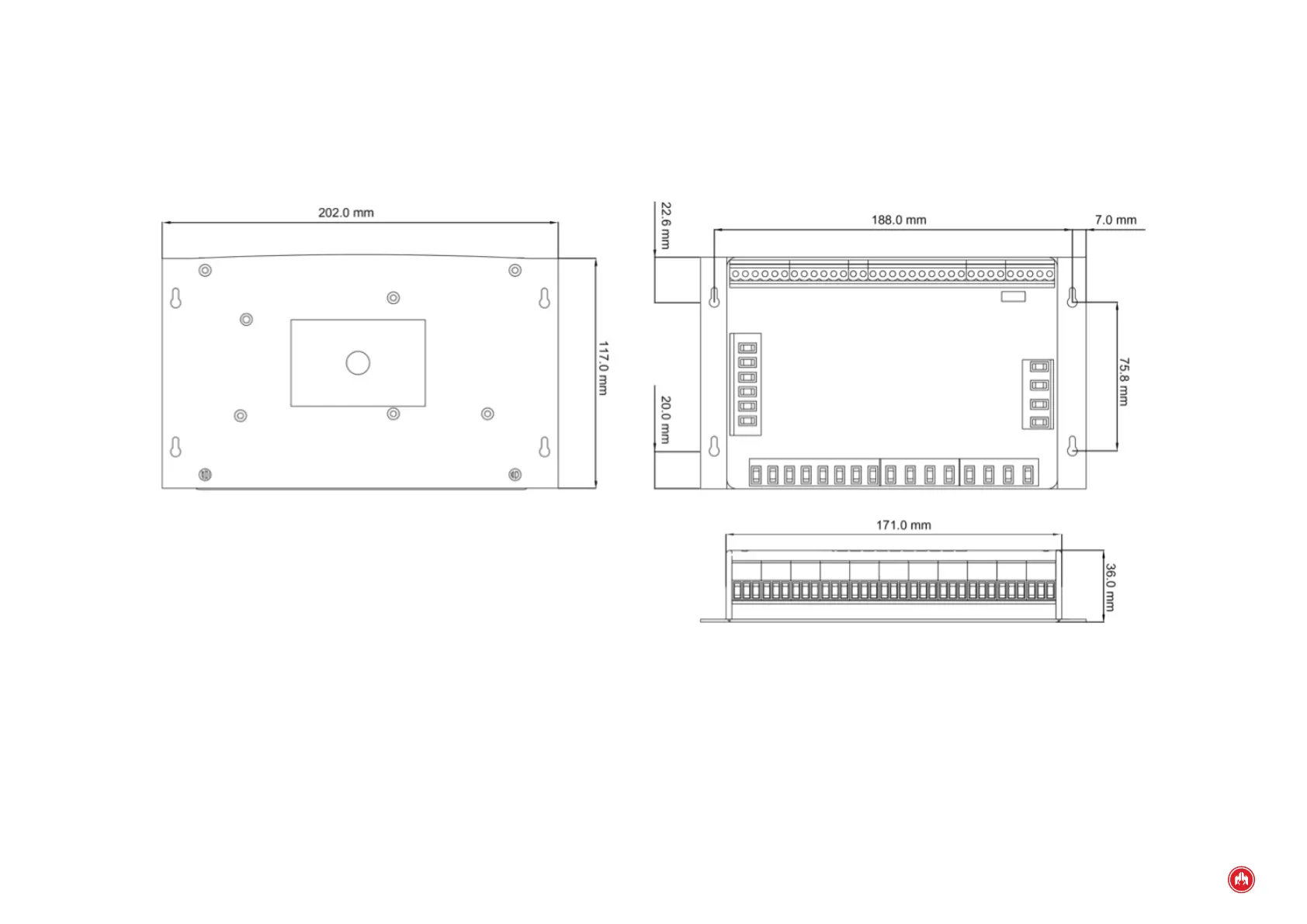
(APPENDIX III) DIMENSIONS, WIRING AND MECHANICAL PARTS | PAGE 91
Signal Description Type Characteristics
VR1 R-phase voltage Input Analogue input for volt-
age measurement
VRN Neutral Input Analogue input for volt-
age measurement
Genset three-phase voltage input
VG3 T-phase voltage Input Analogue input for volt-
age measurement
VG2 S-phase voltage Input Analogue input for volt-
age measurement
VG1 R-phase voltage Input Analogue input for volt-
age measurement
VGN Neutral Input Analogue input for volt-
age measurement
Voltage free relay outputs
CRC C network breaker Output Voltage free relay
output
CRNC NC network breaker Output Voltage free relay
output
CRNA NA network breaker Output Voltage free relay
output
CGC C genset breaker Output Voltage free relay
output
CGNC NC genset breaker Output Voltage free relay
output
CGNA NA genset breaker Output Voltage free relay
output
SCC Circuit breaker C Output Voltage free relay
output
SCNC Circuit breaker NC Output Voltage free relay
output
SCNA Circuit breaker NA Output Voltage free relay
output
BTC Fuel transfer pump C Output Voltage free relay
output
BTNA Fuel transfer pump NA Output Voltage free relay
output
The USB connector complies with the standard 2.0.
To power the control unit, it is recommended that a cable be used with a
cross-section of 1 mm
2
.
The equipment must be isolated or disconnected before connecting the voltage
input for the generator, as there is a risk of danger.
A cable with a cross-section of 2.5 mm
2
must be used for +BAT, ARR, PR and PC
connections. For the rest of the connections it is recommended that a cable be
used with a cross-section of 1 mm
2
.
The control unit must be mounted at the front of an electrical panel, if possible in
the centre to allow easy wiring.
There are no special ventilation requirements due to the low power consumed by
the control unit.
The surface areas of the equipment and the external face should be cleaned with
a damp cloth.
The equipment is included within the measurement category CAT III 600 V for
measurements performed in the building installation.
Disconnection means should be incorporated to the xed installation in accord-
ance with installation regulations. Such means must have contact separation for
all poles that provide full disconnection in category III overvoltage conditions.
The disconnecting means must be accessible by the user. The negative terminal
of the battery, the chassis of the electrical panel and the chassis of the genera-
tor set must all be earthed.
The manufacturer is not liable for any damage caused by not following the war-
nings and / or recommendations indicated in the manual, since the protection
ensured by the equipment may be compromised.
Maximum height assigned above sea level is 2000.
THIS EQUIPMENT CAN GENERATE RISK OF DAMAGE IF HANDLED IMPROPERLY.
IT MUST BE INSTALLED BY QUALIFIED PERSONNEL.
IT IS NECESSARY TO CONSULT THE DOCUMENTATION OF THE EQUIPMENT.
ATTENTION: RISK OF DAMAGE.