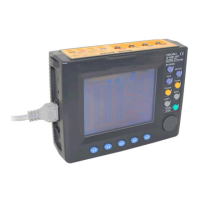
The wiring check result is NG.
Check the following:
Issue What to check Reference
The voltage
input is NG.
• Are you sure that the voltage clip is connected to the
metallic part of the object to be measured?
(p.19)
• Is the voltage cord properly inserted into the voltage
input terminal of the 3169?
(p.11)
• Is the voltage cord properly inserted into the voltage
clip?
(p.10)
The current
input is NG.
• Is the clamp-on sensor securely inserted into the
cur-rent input terminals?
(p.12)
• Is the set current range too large for the input?
If the current range is too large, change the current
range setting to a lower range to have the measure-
ment values more than 5% of the set range.
(p.21)
The voltage
phase is NG.
• Are the voltage cords properly connected?
(To both the object under measurement and the
instrument)
(p.11)
(p.19)
The current
phase is NG.
• Does the current flow direction arrow of the clamp-
on sensor point to the load side?
(p.19)
• Are the clamp-on sensors properly connected?
(To both the object under measurement and the
instrument)
(p.12)
(p.19)
The phase
difference (I-U)
is NG.
• Are the voltage cords and clamp-on sensors prop-
erly connected?
(To both the object under measurement and the
instrument)
(p.11)
(p.19)
• Does the current flow direction arrow of the clamp-
on sensor point to the load side?
(p.19)
• Is the power factor of the line to be measured 0.5 or
less? If the power factor is less than 0.5, the phase
difference (I-U) will show NG even if the wires are
properly con-nected.When the connection is visually
confirmed as being appropriate, the measurement
values will be correct even if a NG judgment is given.
−
The voltage bal-
ance is NG.
• Does the connection method of the line to be mea-
sured differ from that set?
(p.15)
• Are you sure that the voltage clip is connected to the
metallic part of the object to be measured?
(p.19)
• Is the voltage cord properly inserted into the voltage
input terminal of the 3169?
(p.11)

 Loading...