26
Chapter 2 Measurement Procedure
COSφ
U, I
P
U, I
S
U, I
1φ P
SINφ
U, I
COSφ
U, I
φ
U, I
1φ PF
COSφ
U, I
P
U, I
S
U, I
3φ PF
SINφ
U, I
φ
U, I
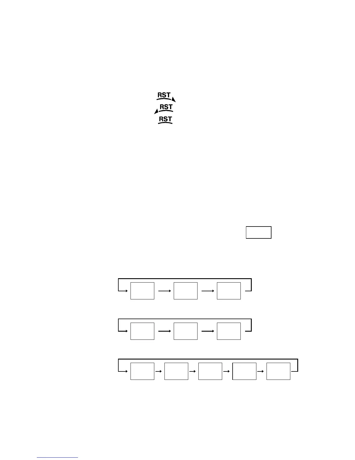
2. Connect the voltage cord to the unit, then connect
the red cord, black cord, and yellow cord to the
circuit under measurement according to prescribed
connections. For a three-phase circuit, the unit will
display the results of phase detection as follows:
Normal phase
Reverse phase
Missing phase
3. Open the tip of the clamp core and clamp the
conductor (on the side to which the red voltage cord
is connected) roughly into the center of the clamp
core, then conduct measurement. In this operation,
clamp the conductor in such an orientation that the
arrow mark on the clamp sensor surface points to
the load side from the power supply side.
4. Select active power, apparent power, power factor,
phase angle, or reactive factor with the
Watt
key.
Note that the 1φ P meter does not display phase
angle and reactive factor. The 1φ PF meter does not
display active power and apparent power.