65
Connecting the Cables
Connecting external control signals
This section describes how to connect external control signals to the instrument’s external control
terminals. You can choose functions using external I/O.
External input: You can control when to start and stop the instrument and input trigger signals.
See “8.3 Conguring External Input/Output (I/O) Terminals” in the Instruction Manual.
External output: You can output signals when a trigger is activated.
See “Trigger output” in the Instruction Manual.
You will need: a at-head screwdriver (with a tip width of 2.6 mm) and an input cable (for pulse
measurement)
Recommended wire diameter
Single-wire Diameter of 0.32 mm to 0.81 mm (AWG 28 to 20)
Standard wire 0.08 mm
2
to 0.32 mm
2
(AWG 28 to 20)
Standard stripping length 10 mm
1
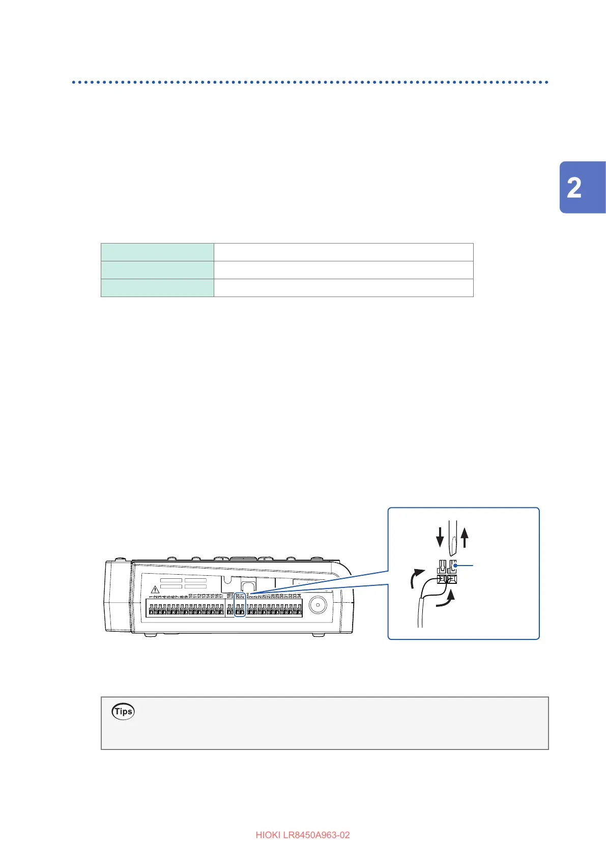
Position the instrument so that the external control terminals on its side are facing you.
2
Press down on the terminal button with the at-head screwdriver.
3
Insert the cable into the terminal hole while depressing the button.
4
Remove the at-head screwdriver from the button.
The cable will be locked in place. Pull gently on the cable and verify that it does not come out.
5
Press down on the GND terminal button with the at-head screwdriver.
There are 10 GND terminals. The wire can be connected to any of the GND terminals.
6
Insert the cable into the terminal hole while depressing the button.
7
Remove the at-head screwdriver from the button.
The cable will be locked in place. Pull gently on the cable and verify that it does not come out.
22 44
33
Example connecting to external input 2
and GND
Terminal
button
How to check the pin assignments of the external control terminals
Press the QUICK SET key, and choose [External connection guide]. Names of the external
control terminals will be displayed.
Making Connections (Preparing for Measurement)

 Loading...


