55
Connecting the Cables
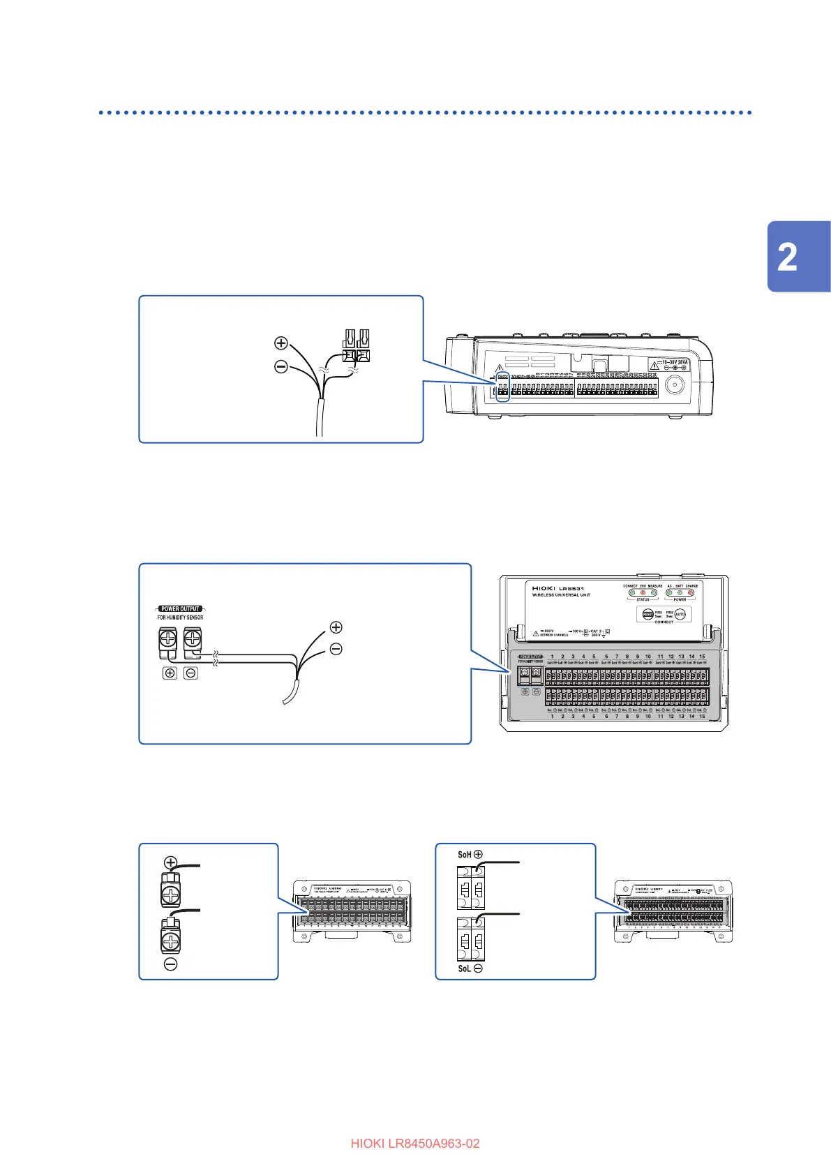
Connecting the Humidity Sensor
Applicable modules: U8550, U8551, U8552, LR8531
You will need: a at-head screwdriver (with a tip width of 2.6 mm) and the Z2000 Humidity Sensor
1
Open the terminal block cover.
2
Connect the Z2000 Humidity Sensor’s power cable to external control terminal voltage
output terminal 1 or 2.
Connect the red cable to the “VOUTPUT1” terminal or the “VOUTPUT2” terminal and the black
cable to the “GND” terminal.
To positive terminal of module
To negative terminal of module
External control
terminal
To supply power to the Z2000, set Voltage output terminals 1 or 2 to [12 V].
See “8.1 Conguring Voltage Output (VOUTPUT)” in the Instruction Manual.
With the LR8531, you can connect the Humidity Sensor’s power cable to the module’s Z2000
Humidity Sensor power supply terminal.
Connect the red cable to the positive terminal and the black cable to the negative terminal.
To positive terminal of
module
To negative terminal of
module
To power terminal
Black (ground)
Red (7 V)
3
Connect the Z2000’s measurement cable to the input channel’s push-button terminal or
screw terminal.
Connect the yellow cable to the positive terminal and the green cable to the negative terminal.
Yellow
(positive)
Green
(negative)
Yellow
(positive)
Green
(negative)
4
Pull gently on the cable and verify that it does not come out.
5
Ax the Z2000 to the measurement target.
6
Close the terminal block cover.
Making Connections (Preparing for Measurement)
 Loading...


