58
Connecting the Cables
Connecting a strain gage or converter
Applicable modules: U8554, LR8534
You will need: a at-head screwdriver (with a tip width of 2.6 mm) and either a strain gage or a
strain gage-type converter
Recommended wire diameter
Single-wire Diameter of 0.32 mm to 1.29 mm (AWG 26 to 16)
Stranded wire 0.2 mm
2
to 0.52 mm
2
(AWG 24 to 20)
Standard stripping length 9 mm
• Choose a strain gage whose gage resistance value is 120
Ω
. If you plan to use a 350
Ω
strain
gage, add a separate bridge box and use the same connection as for the 4-gage method
(converter).
• Choose a strain gage-type converter that supports a bridge voltage of 2 V DC.
• For more information about measuring strain, see “11.2 Measuring Strain” in the Instruction
Manual.
NOTICE
Do not bend, pull on, or twist cables, including where they connect, excessively.
Doing so could cause a wire break into the cable.
• Keep the cables away from power lines and ground lines.
• When measuring with a voltage range of 5 mV or less, measurement may be aected by the
thermal electromotive force of wires and connectors.
• Perform auto-balancing using the same wires and connectors as will be used in measurement.
• All channels in the U8554 and LR8534 terminal block have a common E terminal (GND).
• If connecting the lead wires for the strain gage or other sensor directly, strip back about 9 mm of
insulation from the tip of each lead wire rst.
• When using a strain gage, connect lead wires of the recommended wire diameter using the gage
terminals or use a strain gage with lead wires of the recommended wire diameter.
• If the sensor has a connector (NDIS connector, etc.) like a strain gage-type converter, use the
connection cable supplied by the sensor manufacturer to connect it.
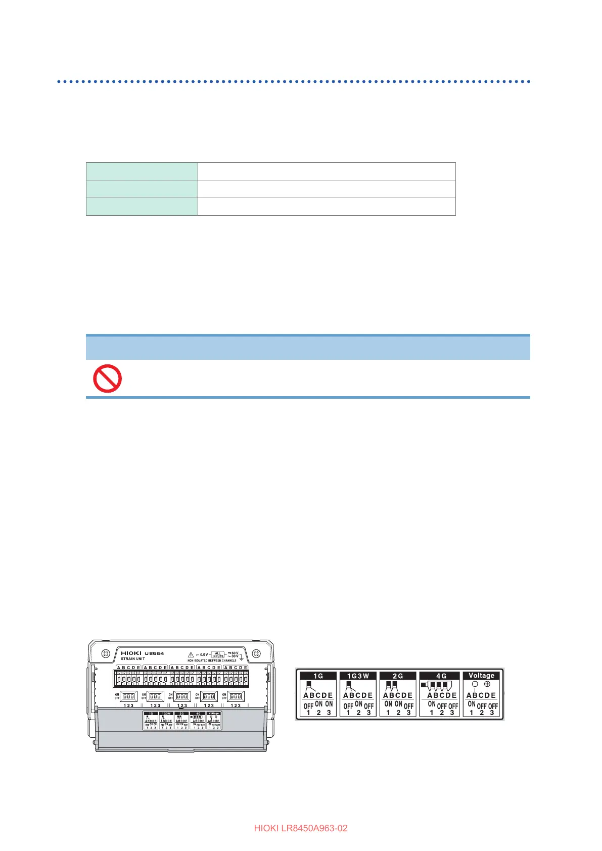
Axing connection conrmation labels
Ax the included connection conrmation labels as desired (for example, on the back of the
terminal block cover).
Connection conrmation label
If label is axed to the terminal block cover

 Loading...


