Installation GRS103
Release
01
03/2022
49
6.6 Grounding the device
The device is grounded via the power supply connection(s).
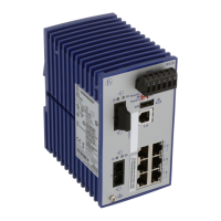
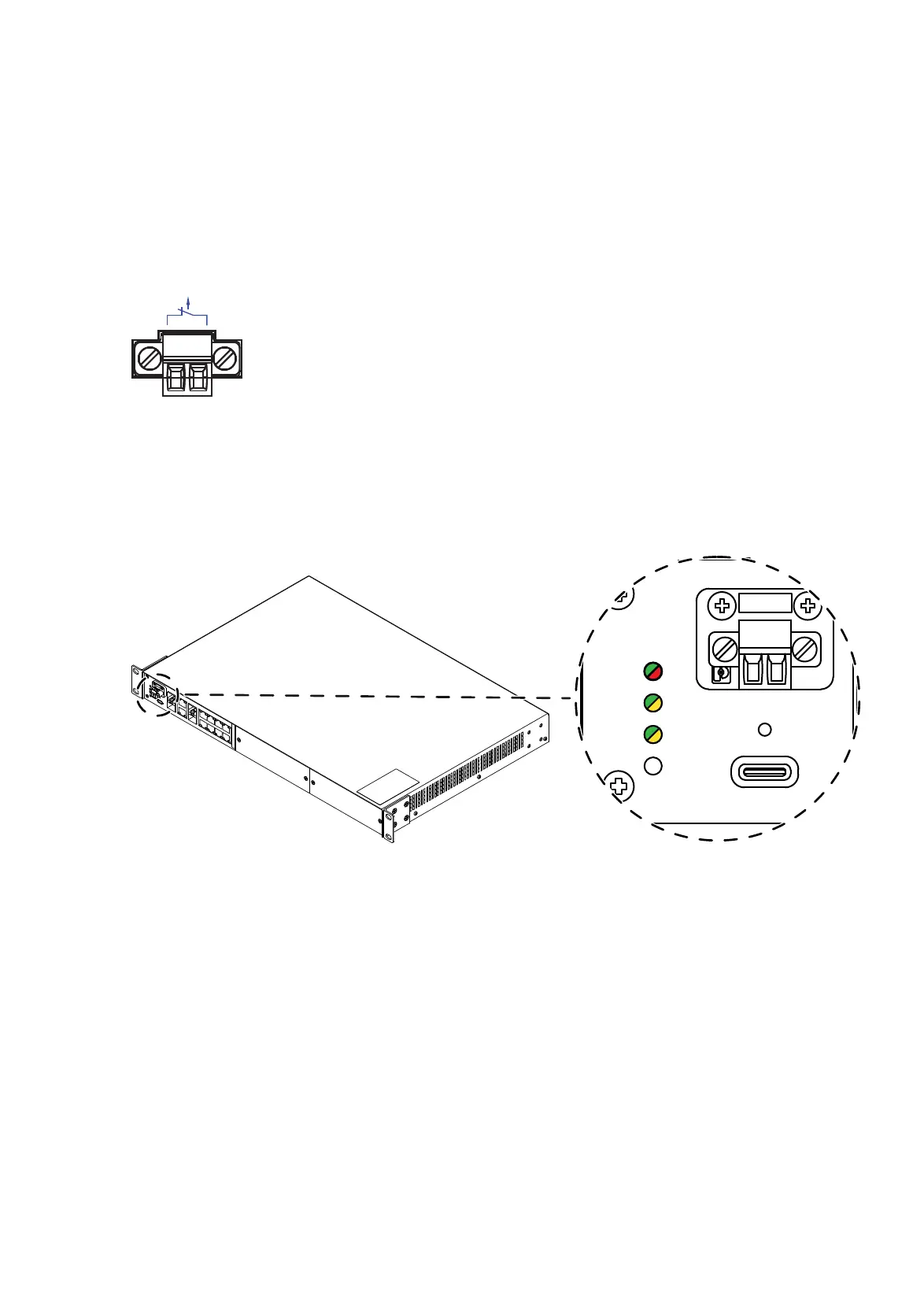
6.7 Connecting the signal contact (optional)
Figure 24: 2-pin terminal block
Note: Observe the electrical threshold values for the signal contact (see on
page 65 “Signal contact”).
Figure 25: Signal contact: 2-pin terminal block with screw lock; position on the device
Perform the following work steps:
Pull the terminal block off the device and connect the signal lines.
Mount the terminal block for the signal contact on the front of the device
using the screw lock. Check whether the terminal block is correctly
plugged and screwed on.
FAULT
USB
Status
P
ACA
Relay
 Loading...