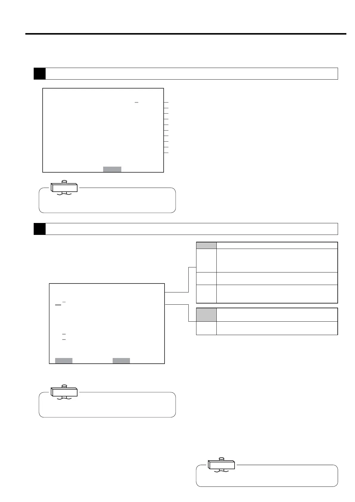
3.3.5 [FUNCTION MENU] −Setting Displays
Confirm settings by compressor alternate operation
specifications and multiple unit control (communication
support). Wiring must be supplied separately for use.
Items for which a dash is displayed next to their num-
ber cannot be set on the LCD monitor.
1. Operation control: Set operation control is dis-
played on the digital monitor.
2. LEAD/LAG operation time: Time setting for alter-
nate operation of a pair of compressors (setting
range: 0.1 – 99.9 hours; initial value: 8.0)
3. Switching conditions: Setting of conditions for
switching operation between a pair of compressors
4. Switching time: Switching time setting if switch-
ing conditions are “parallel” or “interval” (setting
range: 5 – 300 seconds, initial value: 15)
㼇㻹㼁㻸㼀 㻵 㻙㼁㻌 㻿㻱㼀㼀 㻵 㻺㻳㼉
㻝
㻹㻻㻰 㻱 䠖 㻳㻸
㻞䠊㻰㼁㻭㻸 㻌 㼀 㻵㻹㻱䠖 㻌 㻤䠊
㻌 㻿㻺
㻜㼔
㻟䠊㻹㻱 㼀㻴㻻㻰 䠖 㻭㻼
㻠䠊㻿㼃 㻵 㼀㻯㻴㻻㼂㻱㻾䠖 㻜 㻝 㻡 㼟
㻡䠊㻮㻭㻯㻷㼁㻼䠖 㻌 㻌 㻌 㻣㼜
㻻㼂㻾㻾㻸
㼟㼕
㻢䠊㼁㻺㻸㻻㻭㻰 䠖 㻌 㻌 㻌 㻟㼜 㼟 㼕
㻣
㻭㻸㼀䠊㼀 㻵㻹㻱䠖㻌 㻠㻤㻜㻹㻵㻺
㻤
㻯㻻㻺㼀㻾㻻㻸 㻹㻻㻰㻱 䠖 㻮
㻿㻱㼀䠖㻿㼀㻻㻾㻱 㻌㻹㻻㻺䠖㻮㻭㻯㻷
①
②
③
④
⑤
⑥
⑦
⑧
⑨
⑩
㼇㻮㻭㻿㻵㻯 㻿㻱㼀㼁㻼㼉
㼂㻱㻾䠊䠖 㻡䠊㻜
㻡䠊㻜
㻿㻱㻾 㻵 㻱㻿 㻺㻭㻹㻱䠖 㻰㻿㻼
㻯㻻㻻㻸 㻵 㻺㻳 㻹㻱 㼀㻴㻻㻰 䠖 㼃㼀㻾
㻺㻻䠊㻻㻲 㻿㼀㻭㻳㻱 䠖 㻌 㻞
㻼㻙㻿㻼㻱㻯䠖 䚷㻝㻜㻜㼜㼟㼕
㻼 䠊 㻰 㻭 㼀 㻭 䠖 䚷䚷 㻢 㻤 㼜 㼟 㼕
䠟䠰䠖 㻞㻡㻜䠝
㻯㻸 㼀䠊㻰㻱 㻸㻭㼅 䠖 㻌 㻡 㼟
㻵㻼㻵䠖 㻵㻵㻵
㻭㻰㻾㻱㻿㻿 㻺㻻䠊 䠖 㻌 㻝
㻹㻻㻺 䠖 㻮㻭㻯㻷
If using the backup function, switch to the digital moni-
tor and set.
The starter of settings can be confirm the software,
model and setting status of model-specific settings such
as capacity control. (Double asterisks are displayed for
settings that do not require confirmation.)
① Indicates board software version.
② Indicates compressor type.
③ Displays cooling type.
④ Displays the number of compressor stages.
⑤ Displays pressure specification.
⑥ Displays interstage pressure.
⑦ Indicates CT setting value.
⑧ Displays water failure detection conditions for water
cooled compressor.
⑨ Displays status of instantaneous power interruption
(IPI) restart setting.
⑩
Displays compressor number. (Must be distinguished by
number is using communication function.)
The screen provides the model and serves as a target for
setting status. Check the screen when making an inquiry.
IMPORTANT
IMPORTANT
Altered setting values can only be entered when the com-
pressor is not running.
IMPORTANT
5. BACKUP: Setting of pressure to start the backup
compressor when set to backup operation (range: 0.00
– 72 psi, initial value: 7, difference from recovery pres-
sure in the minus direction).
6. UNLOAD:
Pressure setting that manually unloads 1 unit
when the preset pressure is reached in backup operation
(range: 0.00 – 72 psi, initial value: 3, difference from con-
trol pressure in the minus direction).
7. DUAL TIME:
Displays time remaining until switch for
dual / backup operation. Time is not counted down
when operating 2 units for backup operation. When
operation is stopped, remaining time is maintained.
8.
SPEED CONTROL MODE: Displays control mode of V
type. An asterisk is displayed for the Fixed speed type.
19
3. OPERATING THE DSP [How to Use the Liquid Crystal Display (LCD)]
Single Operates compressor independently.
STPR
Multiple
unit
Case where multiple unit control is executed by communication
function of multi roller EX (dedicated panel of NEXT Series).
Unit control is executed by RS485 communication according to
the settings. Requires separate setting of compressor number.
Dual
Operation alternates between a pair of compressors for
a preset amount of time. AUTO light lights.
Backup
Operation mode that adds pressure backup function to
dual operation. When pressure drops, the slave machine
starts. AUTO light lights.
OVER LAP
Method whereby first compressor is stopped after switching time for
the other unit in parallel operation when it is time for dual operation.
Interval
Method of operating the other compressor after stopping the
first one after switching time when it is time for dual operation.
()
1
Model Setting Confirmation
2
Operation Mode Settings
 Loading...