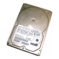
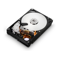
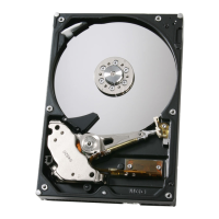
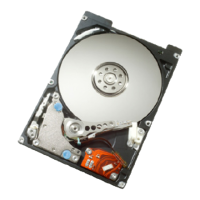
Hitachi hard disk drive specifications
8
List of tables
Table 1 Type and Model# ........................................................................................................................ 13
Table 2 Formatted capacity .................................................................................................................... 18
Table 3 Mechanical positioning performance ....................................................................................... 19
Table 4 World Wide Name Assignment ................................................................................................. 19
Table 5 Command overhead ................................................................................................................... 21
Table 6 Single Track Seek Time ............................................................................................................. 22
Table 7 Latency Time.............................................................................................................................. 22
Table 8 Drive ready time ........................................................................................................................ 22
Table 9 Mode transition times ............................................................................................................... 23
Table 10 Interface connector pins and I/O signals ............................................................................... 26
Table 11 Parameter descriptions ........................................................................................................... 28
Table 12 Temperature and humidity ..................................................................................................... 29
Table 13 Input voltage ............................................................................................................................ 31
Table 14 Power supply current .............................................................................................................. 31
Table 15 Power supply generated ripple at drive power connector..................................................... 32
Table 16 Physical Dimensions ............................................................................................................... 35
Table 17 Random vibration PSD profile break points (operating) ...................................................... 39
Table 18 Random vibration PSD profile break points (nonoperating) ................................................ 40
Table 19 Sinusoidal shock wave............................................................................................................. 41
Table 20 Rotational Shock ...................................................................................................................... 41
Table 21 Sound power levels .................................................................................................................. 42
Table 22 Alternate Status Register ....................................................................................................... 49
Table 23 Device Control Register........................................................................................................... 50
Table 24 Drive Address Register ............................................................................................................ 51
Table 25 Device/Head Register .............................................................................................................. 52
Table 26 Error Register .......................................................................................................................... 53
Table 27 Status Register ........................................................................................................................ 55
Table 28 Reset Response ........................................................................................................................ 56
Table 29 Default Register Values........................................................................................................... 57
Table 30 Diagnostic Codes ...................................................................................................................... 57
Table 31 Power conditions ...................................................................................................................... 60
Table 32 Command table for device lock operation -1 .......................................................................... 67
Table 33 Command table for device lock operation -2 .......................................................................... 68
Table 34 Phy Event Counter Identifiers ............................................................................................... 80
Table 35 READ LOG EXT Log Page 11h data structure definition .................................................... 82
Table 36 SCT Log Page and direction ................................................................................................... 83
Table 37 Identify Device Information Word 206 ................................................................................... 83
Table 38 Output Registers of SCT Command Using SMART ............................................................. 84
Table 39 Input Registers of SCT Command Using SMART ................................................................ 85
Table 40 Input Registers of SCT Command Using Write Log Ext ...................................................... 85
Table 41 Output Registers of SCT Command Using Write Log Ext ................................................... 86
Table 42 Key Sector Format ................................................................................................................... 87
Table 43 SCT Action Code List .............................................................................................................. 87
Table 44 Extended Status Code ............................................................................................................. 88
Table 45 Input Registers of SCT Data Transfer Using SMART .......................................................... 89
Table 46 Input Registers of SCT Data Transfer using Read/Write Log Ext ....................................... 89
Table 47 Input Registers of SCT Status Request Using SMART ........................................................ 90
Table 48 Input Registers of SCT Status Request Using Read Log Ext .............................................. 90
Table 49 Data Format of SCT Status Response ................................................................................... 92
Table 50 SCT Write Same (Inputs) ........................................................................................................ 93
 Loading...

