1
重新设定
显示转换
1
2
Latestshutdown
Secondlatest
shutdown
XX:Shutdown
code
Oldestshutdown
Dischargeairpressuredisplay
SWITCHDISPLAY
Press8times.
Proceedsby1each
timepressed.
Returnsby1each
timepressed.
Returnstodischarge
airpressure.
Historyconsistsof6items.
Todisplayofvarioussettings
Faninvertershutdownhistory.
Mainmotorcontroller
shutdownhistory.
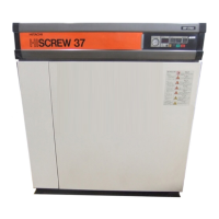
(2) Displaying the Shutdown History
To display shutdown history, proceed as follows:
①
Press the
SELECT
button 8 times.
The screen
displays
“E0.” together with the shutdown code (
see p. 24-25).
The “0” indicates the latest shutdown.
(Automatically
changes to “E.0” when shutdown or alarm occurs.)
②Press the SELECT button. The screen displays “E1.”
together with the shutdown code. The “1” indicates the
second latest shutdown. “1” indicates shutdown that has
occurred before. 6 items from 0 – 5 are recorded. 5 of
“E5.” indicates the oldest shutdown.
③ Press the SELECT button. “E6.” and “E7.” are the shut-
down histories of the controller.
④ Press the RESET button. The screen returns to pressure
monitor display.
1.
Displaying the “XX” is “ ” in the action
①
indicates that
no shutdown histories are stored in the memory. When
contents other than shutdown history are displayed
without resetting shutdown histories, the display returns
to the newest shutdown history display 3 minutes later.
2.
The shutdown histories of the DCBL controller and the
fan inverter are recorded for the latest shutdown only.
Shutdown history is displayed by the shutdown code.
(
See p. 26)
重新设定
1
显示转换
1
2
No.0:CapacityControlMode
A:V+Pmodecontrol
No.2:Cutinpressure1
070: 0.7MPa
No.3:Notused
No.4:Notused
No.6:Cutinpressure2
060: 0.7MPa
No.1:Cutoutpressure1
078: 0.78MPa
No.5:Cutoutpressure2
078: 0.78MPa
No.7:Notused
No.8:Instantaneouspower
interruption(IPI)setting
000: Invalid
No.9:Compressoraddress
001: No.1
SWITCHDISPLAY
Press16times.
Dischargeairpressuredisplay
Proceedsby1
eachtimepressed.
Returnsby1each
timepressed.
Returnsto
dischargeair
pressure.
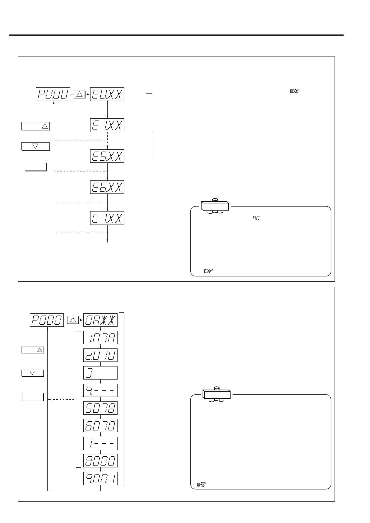
(3) Displaying the Capacity Control Settings
To display the capacity control and pressure settings, proceed
as follows:
① Press the SELECT button 16 times. The screen displays
“0.A ** ” as an example (see the IMPORTANT below).
② Press for each new screen to display the cutout and cuton
pressures.
③ Press the RESET button. The screen returns to what you
have left with the action ① above.
The first screen displays the capacity control mode
symbols: A, L, or U. Each mode consists of the capac-
ity control modes as follows:
A: V+P-mode
U: V+I-mode
The cutin pressure is defined as the pressure as transi-
tion from I-mode capacity control to V-mode capacity
control (CPCS rotation control method).
The cutout pressure is defined as the pressure as tran-
sition from V-mode capacity control to I-mode capacity
control.
(
see p. 15, 31-32)
IMPORTANT
IMPORTANT
10
3. HOW TO OPERATE [How to Use the Digital Monitor and its Controls]
 Loading...