4 Electrical checks of main parts
Outdoor unit
SMGB0135 rev.0 - 06/2020
39
4
4.1.3 PCB for power circuit
Voltage specication of power circuit as shown in below table.
Output Spec Main load Measuring point Example of possible failure mode
5 V 0/P 5
± 0.4
V
Micon,
Thermistor
Tester
+
: L105 (JUMPER)
Tester
-
: D110 (EARTH)
Outdoor not operate, no blinking indication
12 V 0/P 12
± 0.5
V
Micon,
IC2, 3, 4
Relay circuit
Tester
+
: L104 (JUMPER)
Tester
-
: D110 (EARTH)
Outdoor not operate, no blinking indication
16 V 0/P
15.5
V
+ 1.5
- 1.0
IPM for Compressor
IPM for DC fan
Tester
+
: L103 (JUMPER)
Tester
-
: D110 (EARTH)
Stop: LD301 3, 4 or 12 times blinking
B-12 V 0/P
13
V
+ 2.5
- 1.0
Expansion valve
Tester
+
: R120 (B-12 V)
Tester
-
: R120 (B-0 V)
Stop: LD301 5 times blinking
Power circuit for PCB can consider normal if the result is satised with above specication.
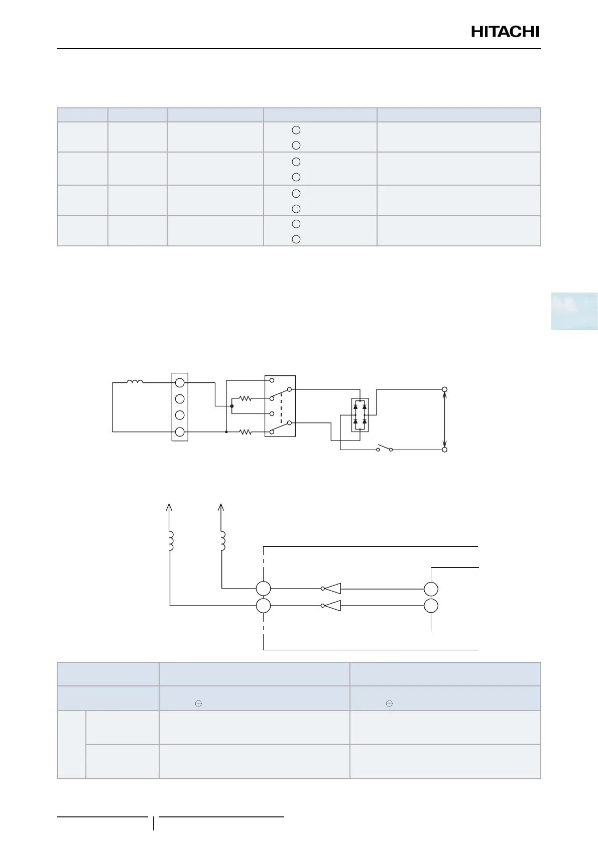
4.1.4 Reversing valve control circuit
This control is used to control de ON/OFF state of the relay and the coil, both of the reversing valve.
The ON/OFF state of the relay depends on the operation mode, as shown in the following table.
If the reversing valve is not powered or the conditions do not correspond to the appropriate ones for the operation mode,
it could indicate failure of the control circuit of the reversing valve.
1
2
3
4
R441
R442
DB2
CN2
AC230V
28
27
12V
12V
28
29
Microcomputer
Reversing valve
(4-way Valve)
Cooling/Heating
switching relay coil
(RL4)
Cooling/Heating
switching relay
(RL4)
Reversing valve
(4-way Valve) relay
(RL3)
Reversing valve
(4-way Valve) relay
coil (RL3)
Reversing valve
(4-way Valve) on
Reversing valve (4-
way Valve) cooling/
heating switching
Cooling Lo
Heating Hi
HIC
Operation mode
Cooling operation
(including forced cooling operation)
(Reference) Heating operation
Tester and CN2 terminal
connection point
⊕ terminal of tester to CN2 pin
terminal of tester to CN2 pin
⊕ terminal of tester to CN2 pin
terminal of tester to CN2 pin
Types of testers
Analog tester
The tester indicates about 80 VDC and returns to 0
V, and indicates about 80 VDC again.
The tester indicates about 160 VDC and returns to
0 V, and indicates about 160 VDC again.
Digital tester
The tester indicates a large value for an instant and
returns to 0 V, and indicates a large value again.
The tester indicates a large value for an instant and
returns to 0 V, and indicates a large value again.
 Loading...