7 Servicing
RPI(L/H)-(0.4-6.0)FSRE - Ducted indoor unit
SMGB0137 rev.0 - 05/2021
232
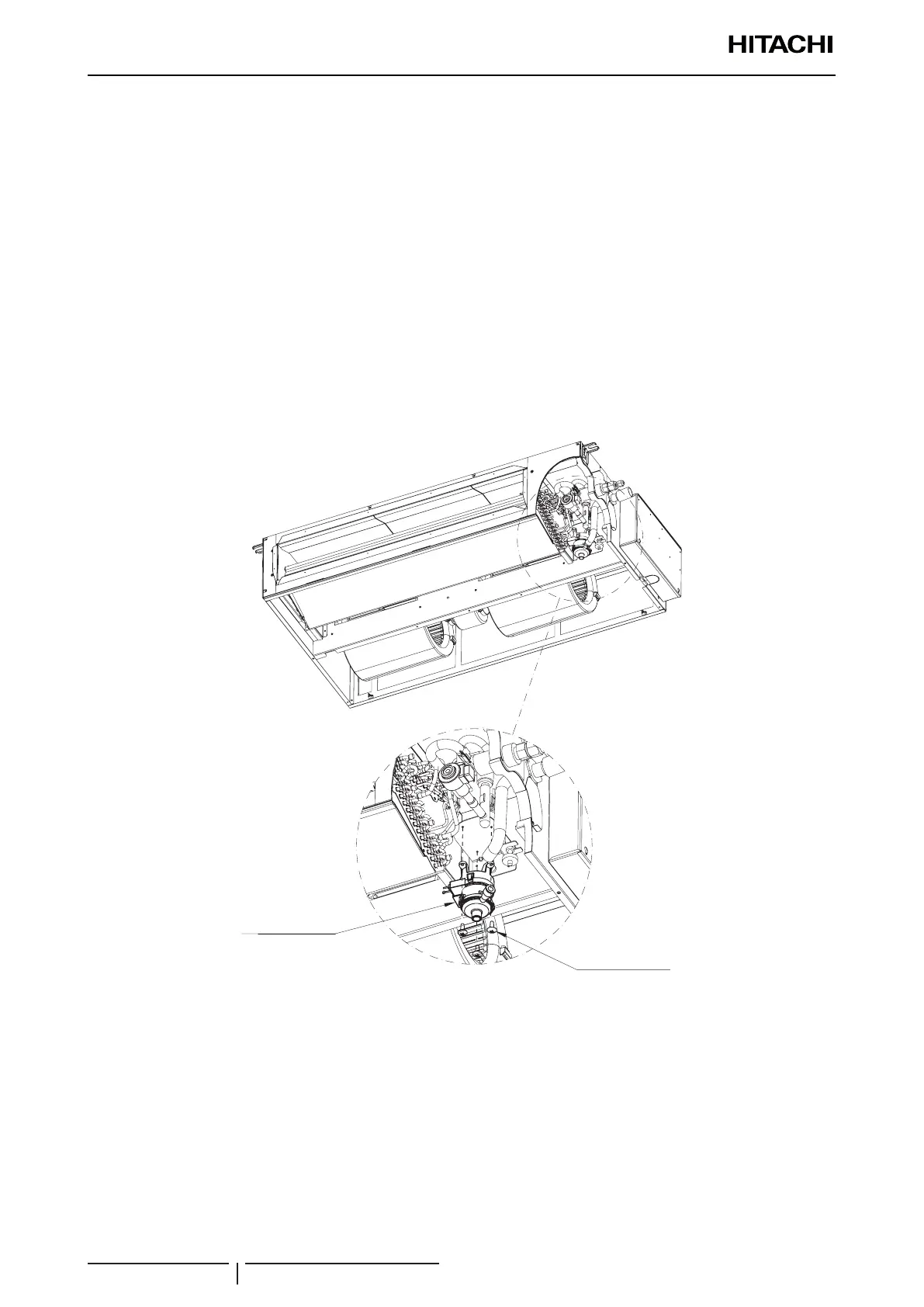
7.5.10 Removal of the drain mechanism
? NOTE
To disconnect and remove the drain mechanism, previously see the chapter corresponding to the wiring diagrams in “3.3 Wiring diagrams”.
1 Remove the motor and service covers as explained in “7.5.4 Removal of the motor cover” and “7.5.5 Removal of the
service cover”.
2 Remove the drain pan as explained in “7.5.6 Removal of the drain pan”.
3 Remove the drain pump support screws and remove it.
4 Remove the electrical box from the unit to connect it to the printed circuit board (PCB) in line with the instructions
given in chapter “7.5.1 Removal of the electrical box”.
5 Seal the drain hose gaskets correctly.
? NOTE
When reassembling the drain pump, pass the cables through the eletrical hose or clamp the cables with several plastic bands along the
outside of the electrical hose.
Bottom side
Drain pump
Drain pump screws
(x3)
 Loading...
