S1 series standard inverter
-28-
COM
PE
+24V
S4
S3
S2
S1
HDIB
PW
HDIA
Multi-function input terminal 1
+10V
AI1
AI2
GND
PE
-10V
(external)
A01
V I
SW2
GND
Analog output
0-10V/0-20mA
Y1
CME
COM
HDO
Optional between high-
speed pulse output and
open collector output
485+
485-
485G
RS485
communication
RO2C
RO2B
RO2A
RO1C
RO1B
RO1A
Relay 1
output
Relay 2
output
ON
OFF
SW3
multi-function
analog input
H1
H2
+24V
S2
S1
Safety
controller
Open circuit
Safety
input
Safety
switch
Y1
output
Safety state
feedback
Multi-function input terminal 2
Multi-function input terminal 3
Multi-function input terminal 4
High speed pulse input terminal
High speed pulse input terminal
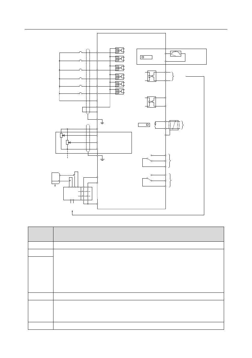
Fig 4.19 Wiring diagram of control circuit (4-400kW)
10V reference power supply
1. Input range: AI1 voltage / current can choose 0–10V / 0–20mA
AI2: -10V – +10V voltage
2. Input impedance: 20kΩ during voltage input; 250Ω during current input
3. Voltage or current input can be set by parameters
4. Resolution ratio: When 10V corresponds to 50Hz, the Min. Resolution ratio is 5mV
5. 25 ° C, When input above 5V or 10mA, the error is ± 0.5%
1. Output range: 0–10V voltage or 0–20mA current
2. Voltage or current output is set by toggle switch SW2
3. 25° C, when input above 5V or 10mA, the error is ± 0.5%
RO1 relay output; RO1A is NO, RO1B is NC, RO1C is common port
 Loading...


