EasyManua.ls Logo

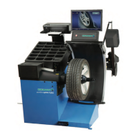
Hofmann ATC 900 User Manual

Hofmann ATC 900
120 pages
To Next Page IconTo Next Page
Page #1 background imageLoading...
Page #1 background image
CTC-CEN Service Manual 07-13 Rev.E
1
ATC 900 – CENTAUR –
MONTY 8600 – VULCAN PRO
SERVICE MANUAL
DO NOT COPY NOR DISTRIBUTE
No part of this document may be photocopied, reproduced, or translated
without prior written consent of Snap-on

Table of Contents

Question and Answer IconNeed help?

Do you have a question about the Hofmann ATC 900 and is the answer not in the manual?

Hofmann ATC 900 Specifications

General IconGeneral
Rim width1.5" - 20"
Rim diameter10" - 30"
Max. wheel weight154 lbs
Wheel Diameter Range10" - 30"
Balancing Accuracy1 g
Power supply230V / 50Hz

Summary

CHAPTER 2 TOOLS AND SAFETY

2.1 Tools and special tools required

Lists standard and specialized tools required for maintenance and repair.

2.2 Important safety instructions

Provides essential safety precautions for operating and servicing the equipment.

2.3 Electrical safety precautions

Outlines critical safety measures to prevent electrical hazards during maintenance.

CHAPTER 4 AC/DC POWER DISTRIBUTION

4.1 Lockout and/or tagout system procedure

Details the steps for safely isolating the machine from its power source.

4.2 Electrical requirements

Specifies the necessary electrical connections and safety features for the machine.

CHAPTER 5 ELECTRIC SECTION

5.1 Power supply cable and plug: check and replacement

Guide for inspecting and replacing the machine's power cable and plug.

5.2 Main rotary switch Q1 # 2-15359A: check and replacement

Procedure to check and replace the main rotary power switch.

5.3 Centerpost motor M3 cable: check and replacement

Instructions for checking and replacing the cable connected to the centerpost motor.

5.4 Centerpost motor M3 # 2-49166A and belt # 8-06831A: check and replacement

Steps to check and replace the centerpost motor and its belt.

5.5 Lower bead breaker arm actuator M1 # EAA0377G02A: check and replacement

Guide for checking and replacing the lower bead breaker arm actuator.

5.6 Transformer T3 # 7-02702A: check and replacement

Procedure for checking and replacing the T3 transformer.

5.7 Centerpost switch S1 # 2-15259A: check, adjustment and replacement

Instructions for checking, adjusting, and replacing the centerpost switch.

CHAPTER 6 ELECTRONIC SECTION

6.1 Inverter T1 # EAA0358G49A: check and replacement

Guide to check and replace the T1 inverter.

6.2 Inverter T1 # EAA0358G49A Rev.B: Firmware update

Procedure for updating the firmware of the T1 inverter.

6.3 CPU board A1 # EAP0275G50A: check and replacement

Instructions for checking and replacing the CPU board.

6.4 Bead breaker arms potentiometers B1 and B2 # EAA0377G07A: check and replacement

Guide for checking and replacing the bead breaker arm potentiometers.

CHAPTER 7 PNEUMATIC SECTION

CHAPTER 8 MECHANICAL SECTION

8.4 Gear box: check and replacement

Instructions for checking and replacing the gearbox.

CHAPTER 9 TROUBLE SHOOTING

Related product manuals