CTC-CEN Service Manual 07-13 Rev.E
36
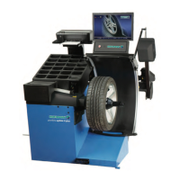
4. Position the red crocodile to the green wire and the
black one on the white wire of the potentiometer.
5. Turn the machine on.
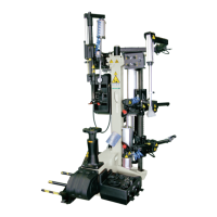
6. Move the bead breaker arms to maximum error point.
7. Read the value displayed on the multimeter.
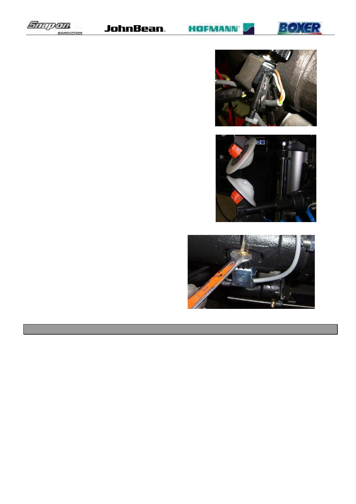
8. Unlock the potentiometer counter nut.
9. Turn the potentiometer with a flat screwdriver
subtracting 0,020 Vdc from the value
displayed.
10. Lock the counter nut again.
11. Calibrate the machine.
12. Check if the arms are better aligned.
13. Turn the machine off.
14. Install the potentiometer cover again.
6.6 BEAD BREAKER ARMS CALIBRATION SW 1.0.3 / 1.0.4
: 30’.
: 5mm Allen.
The bead breaker arm potentiometers calibration can be performed by pressing the following button placed on the
CPU board inside of the electric box.
SW1 Inward lower bead breaker arm motion (enable during calibration phase only).
SW3 Outward lower bead breaker arm motion (enable during calibration phase only).
SW2 Calibration button (see below).
SW4 On/Off laser pointer button. During the calibration is used to exit from calibration.
 Loading...