6.0 THROTTLE BODY & CABLE BRACKET INSTALLATION
1. Disconnect the battery and remove the air cleaner.
2. Before disconnecting any vacuum hoses, it is a good idea to sketch out the vacuum hose routing. Using masking tape and a
permanent marker, mark all the vacuum hoses, vacuum sources, and ports before removing the old fuel delivery system.
3. Remove and discard the fuel line that connects to the carburetor from the mechanical fuel pump. This will not be needed in the
installation. Remove the throttle return springs and keep for later installation.
4. Remove carburetor (if applicable) and clean mounting flange ensuring no debris falls into intake manifold.
5. Install the four Manifold Flange Studs (Item 9) into the intake manifold. Install the Flange Gasket (Item 8) between the manifold
and the STEALTH TERMINATOR™. Check for sufficient thread engagement of the throttle body hold down studs and nuts.
DANGER! Check for proper clearance between engine components, such as the distributor, coil, etc., and the throttle body.
Also check for clearance between the air cleaner and hood. If any interference is found, correct the condition before
continuing. Failure to do so can result in damage to the engine components, throttle body, or hood.
6. Position the STEALTH TERMINATOR™ Throttle Body Assembly (Item 4) over the manifold flange studs with the throttle lever
located on the driver’s side.
7. Place the Throttle Bracket (Item 17) for your application over the rear driver’s side stud and use ¼-20 x 5/8 SHCS (Item 18) and a
Lockwasher (Item 23) to secure.
8. Using the supplied 5/16-24 Nuts and Washers (Items 6 & 7), tighten the throttle body down in a criss-cross pattern. Proper torque is
5-7 ft./lbs. DO NOT OVERTIGHTEN!
6.1 Throttle Connections
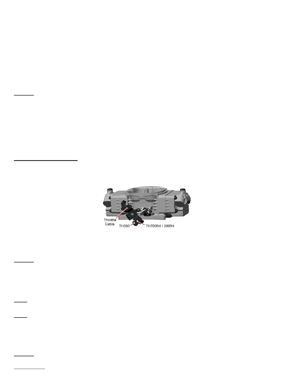
1. The throttle body is designed to provide the proper cable geometry for TH350, TH200R, and TH700R4 transmissions as shown in
Figure 8. Install the Throttle and Transmission Studs (Items 19, 20, 21, and/or 22) for your application in their dedicated holes and
secure each with a Lock Washer (Item 23) and 1/4-28 Nut (Item 24).
Figure 8
2. Once the throttle linkage is attached, have an assistant get in the vehicle and fully actuate the throttle controls. Make the necessary
adjustments to the throttle linkage to ensure that the throttle plates are vertical when the throttle control is wide open. Work the
throttle linkage back and forth several times to ensure it operates smoothly with no binding or sticking.
DANGER! A sticking throttle may result in uncontrolled engine or vehicle speed. This could cause property damage, personal
injury, or death. A sticking throttle may be caused by improperly installed throttle cables, lack of clearance for any of
the throttle linkage, or by a binding throttle linkage. Check all throttle cables for proper installation and alignment.
Actuate the throttle to check for any potential binding or clearance problems. Repair any problems before continuing.
3. If the vehicle is equipped with an automatic transmission, ensure that the transmission kickdown is properly adjusted. Follow the
vehicle manufacturer’s procedure for the correct adjustment procedure.
NOTE: On late model GM and Ford overdrive transmissions with a lockup torque converter, make sure the lockup function is properly
retained. Failure to do so will result in premature transmission failure.
NOTE: On Chrysler vehicles, a lever extension will be needed, Holley PN 20-7. Van applications may require the use of throttle lever
extension Holley PN 20-14.
4. Install external throttle return springs that you previously removed from the carburetor. External springs should be used in addition to
the springs on the throttle body itself. Have an assistant get in the vehicle and fully depress the accelerator pedal. Make the
necessary adjustments to the throttle linkage to insure that the throttle reaches wide-open position when the accelerator is depressed.
Work throttle linkage back and forth several times to ensure that it operates smoothly with no binding or sticking.
DANGER! Failure to attach the throttle return spring or a sticking throttle may result in uncontrolled engine or vehicle speed,
which could cause personal property damage, serious injury, or death.
 Loading...