Throttle Body Service Parts: QTY P/N
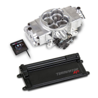
STEALTH TERMINATOR™ Sub-Harness 1 558-441
Intake Air Temperature (IAT) Sensor 1 554-121
Terminator 80PPH Fuel Injector (requires purchase of 4) 1 522-801
Manifold Absolute Pressure (MAP) Sensor 1 554-120
Idle Air Control (IAC) Motor 1 543-105
Throttle Position Sensor (TPS) 1 9920-110
40 AMP Relay 1 534-26
Transmission Harness 1 558-405
Optional Parts:
Small Cap GM HEI Ignition Adapter 1 558-304
Ford TFI Ignition Adapter 1 558-305
Ford Transmission Kickdown Bracket Kit 1 20-152
0-100 PSI Pressure Transducer (1/8” NPT; for monitoring fuel pressure) 1 554-102
3.0 TOOLS REQUIRED FOR INSTALLATION
An assistant is necessary for some installation and adjustment procedures and should be present for safety reasons.
WARNING! Disconnect battery before proceeding with any installation.
4.0 OXYGEN SENSOR INSTALLATION
IMPORTANT! Position and support your vehicle on a suitable surface. USE CAUTION AND WORK ONLY ON A LEVEL SURFACE
USING JACKS AND JACK STANDS OF SUFFICIENT CAPACITY TO LIFT AND SUPPORT YOUR VEHICLE. NEVER
WORK UNDER A VEHICLE SUPPORTED BY A FLOOR OR BUMPER JACK. Use of a two-post under arm lift or four-
post drive-on lift will considerably reduce the time and effort required to complete the installation. MAKE SURE LIFT
LOCKS ARE ENGAGED BEFORE WORKING UNDER THE VEHICLE.
OXYGEN SENSOR WELD RING INSTALLATION (Recommended):
WARNING! Failure to disconnect the AIR pump or locating the oxygen sensor downstream from AIR injection will result in an extremely
rich mixture, which could cause drivability problems and severe engine damage. If disconnecting AIR pump, check with local
ordinances for the legality of this procedure in your area.
1. Locate a position for the oxygen sensor as close to the engine as possible. The oxygen sensor should be mounted at a point where it
can read a good average of all the cylinders on one bank. This would be slightly after all the cylinders merge. If you have long tube
headers, mount the sensor approximately 1-10” after the collector. You must have at least 18” of exhaust pipe after the sensor. If
your vehicle has catalytic converters, the oxygen sensor MUST be located between the engine and the catalytic converters.
2. Ensure the location for the sensor is at the angle in Figure 2. This will help prevent condensation in the exhaust tubing from entering
the sensor. The sensor can be mounted on either side of the tubing.
3. Drill a 7/8” hole in the intended location for the sensor. Weld the Oxygen Sensor Weld Ring (Item 2b) into the 7/8” hole. Weld all
the way around the boss to insure a leak proof connection. Install the Oxygen Sensor (Item 1) into the weld ring and tighten
securely. It is a good idea to add anti-seize to the threads to aid in removal. Do not get any anti-seize on the tip of the sensor.
NOTE: Never run the engine with the oxygen sensor installed if it is not plugged in and powered by the ECU, or it will be damaged. If
you need to plug the hole temporarily, use an O2 sensor plug or a spark plug with an 18mm thread.
CLAMP-ON OXYGEN SENSOR BUNG INSTALLATION (Optional):
WARNING!
Failure to disconnect the AIR pump or locating the oxygen sensor downstream from AIR injection will result in an extremely rich mixture,
which could cause drivability problems and severe engine damage. If disconnecting AIR pump, check with local ordinances for the legality
of this procedure in your area.
Your vehicle may already have an O2 sensor bung welded into the exhaust. This bung location needs to be verified before using it with
the Oxygen sensor included in the Sniper EFI system. Ideally, the bung will be 6-10 inches after the collector for a true reading of all
cylinders and have a minimum of 18” length past the sensor location. If the vehicle is equipped with a catalytic converter, the bung must
be between the engine and the catalytic converter. The bung also must be on the top side of the tube so moisture cannot collect on the
oxygen sensor. If there is an acceptable bung already present, go ahead and tighten the oxygen sensor supplied with your Sniper EFI in
 Loading...