6. OPERATION
The head spring holding xture is cylind-
rical. Loosen three set screws A and nuts
(See Figure 14 - only two are visible on
the picture).
Position the new chuck and x it using
the same set screws and nuts.
1. See Figure 16
Unscrew the two fastening screws
B and remove the protective cover.
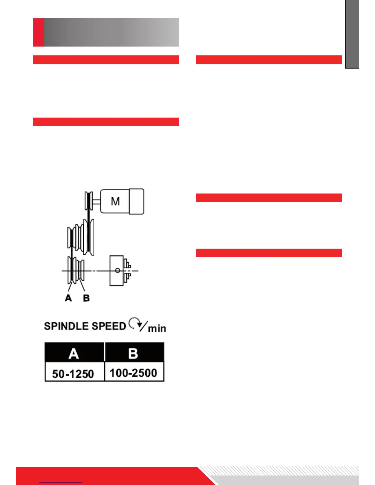
2. See Figure 17
Adjust the V-belt C to the
corresponding position.
There are two V-belt positons:
Pos. A (outer pulleys) for lower speed
range.
Pos. B (inner pulleys) for higher speed
range.
3. Tighten the tension pulley and
fasten the nut again.
REPLACEMENT OF CHUCK
CHANGE SPEED
TOOL SET-UP
Clamping the turning tool into the tool-
holder.
The tool must be clamped rmly. When
turning, the tool has a tendency to bend
under the cutting force generated during
the chip formation. for best results, tool
overhang should be kept to a minimum
of 3/8“ (~ 9mm) or less.
The cutting angle is correct when the cut-
ting edge is in line with the center axis
of the workpiece. The correct height of
the tool can be achieved by comparing
the tool point with the point of the center
mounted in the tailstock. If necessary,
use steel spacer shims under the tool to
get the required height (see Figure 15).
See. Figure 19
Apron travel, cross travel and top slide
handwheel can be operated for longitudi-
nal or cross feeding.
See. Figure 18
Use the table A on the lathe for selecting
the feed speed or the thread pitch. Ad-
just the change gear if the required feed
or thread pitch cannot be obtained with
the installed gear set.
1. Disconnect the machine from the
power source.
2. Unscrew the two fastening screws
and remove the protective cover.
MANUAL TURNING
LONGITUDINAL TURNING WITH AUTO-FEED
ENGLISH