5. 5 ELECTRIC STARTER
cover and adjust the horn by turning the adjusting
screw slowly _ a notch at a time in both 'direc-
tion until properly adjusted. {there are 20 notches
for each turn of the adjusting screw)
Turning in the clockw ise direction will increase
the loundness, turning counter clockwise will
reduce the loudness and eliminate the
vibrating
noise. Do -not turn the adjusting screw more that
two turn in either direction.
C. Tail-Stop light
The tail-stoplight incorporates two within the bulb,
Bulb specification
For USA export
12 V-23/7 W
For general export
12 V-25/8 W
When replacing bulbs, always use a ba\b of the
specified roting.
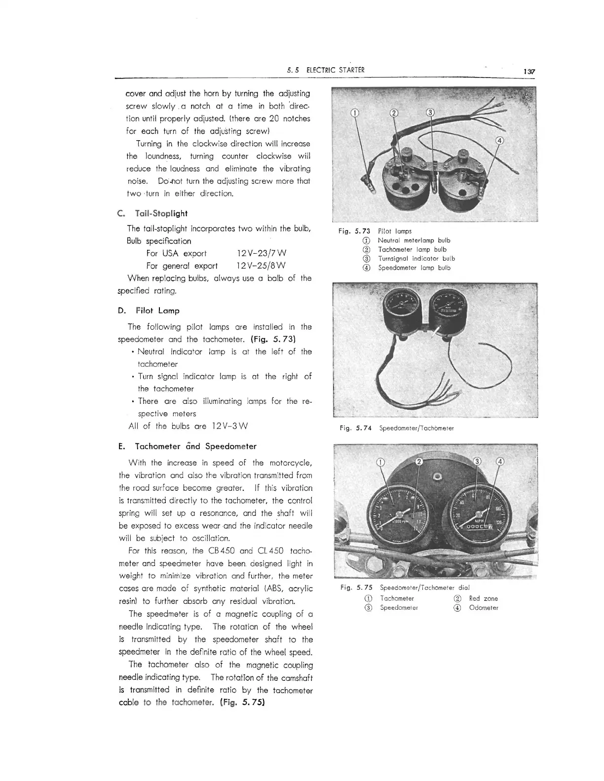
D. Filot Lamp
The following pilot lamps are installed in the
speedometer and the tachometer.
(Fig. 5. 73)
• Neutral indicator lamp is at the left of the
tachometer
• Turn signal indicator lamp is at the right of
the tachometer
• There are also illuminating lamps for the re-
spective meters
All of the bulbs are 12
V-3 W
E. Tachometer and Speedometer
With the increase in speed of the motorcycle,
the vibration and also the vibrat ion transmitted
from
the road surface become greater. If this vibration
is transmitted directly to the tachometer, the control
spring wi ll set up a resonance, and the shaft wi ll
be exposed to excess wear and the indicator needle
will be subject to oscillation.
For this reason, the CB 450 and CL 450 tacho-
meter and speedmeter hove been designed light in
weight to minimize vibra tion and further, the meter
cases are made of synthetic material (ABS, acrylic
resin) to further absorb any residual vibration.
The speedmeter is of a magnetic coupling of a
needle indicating type. The rotation of the wheel
is transmitted by the speedometer shaft to the
speedmeter in the definite ratio of the wheel speed.
The tachometer also of the magnetic coupling
needle indicating type. The rotation of the camshaft
is transmitted in definite ratio by the tachometer
cable to the tachometer.
(Fig. 5. 75)
fig. 5. 73 Pilot lamps
CD Neutral meterl amp bulb
® Tachometer lamp bulb
@ Turnsignal indic ator bulb
© Speedometer lamp bulb
Fig.
5. 74 Speedometer/Tachometer
Fig.
5. 75 Speedometer/Tachome ter dial
CD Tachometer ® Red zone
@ Speedometer © Od ometer
137
-l
I
___ J
 Loading...