3. 2 CYLINDER HEAD
31
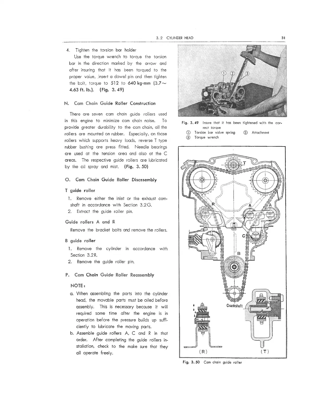
4. Tighten the torsion bar holder
Use the torque wrench to torq ue the torsion
bar in the direct ion marked by the arrow and
after insuring that it has been torqued to the
proper value, insert a dowel
p;n and then tighten
the bolt, torque to
512 to 640 kg-mm (3.7-
4.63 ft. lb.). (Fig. 3. 49)
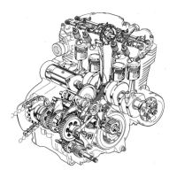
N. Cam Chain Guide Roller Construction
There ore seven cam chain guide roller s used
in this engine to minimize cam chain noise. To
provide greater durability to the cam chain, all the
rol lers ore mounted on rubber. Especially, on those
rollers which supports heavy loads, reve rse T type
rubber bushing are press fitted . Needle bearings
are used at the tension area and also at the C
areas. The respective guide rollers are lubricated
by the oil spray and mist.
(Fig. 3. 50)
0. Cam Chain Guide Roller Disassembly
T guide roller
1 . Remove either the inlet or the exhaust cam-
shaft in accordance with Section 3.2G.
2. Extrac t the guide rolle r pin.
Guide rollers A and R
Remove the bracket bolts and remove the rollers.
B guide roller
1. Remove the cyli nder in accordance with
Section 3. 2
R.
2. Remove the guide roller pin.
P. Cam Chain Guide- Roller Reassembly
NOTE:
a. When assembling the parts into the cylinder
head, the movable parts must be oiled before
assembly. This is necessary because it will
required some time ofte r the engine is in
operation before the pressure builds up suffi-
ciently to lubricate the moving ports.
b. Assemble guide rollers
A, C and R in that
order. After complet ing the guide rollers in-
stallation, check to the make sure that they
all operate free ly.
Fig. 3. 49 Insure that it hos been ti ghtened w.ith the cor-
rect torque
CD Torsion bar valve spring
@ Torque wre nch
( R)
Fig. 3. 50 Com chai n guide roller
® Attachment
(T)
 Loading...