3. 5 UPPER AND LOWER CRANKCASE
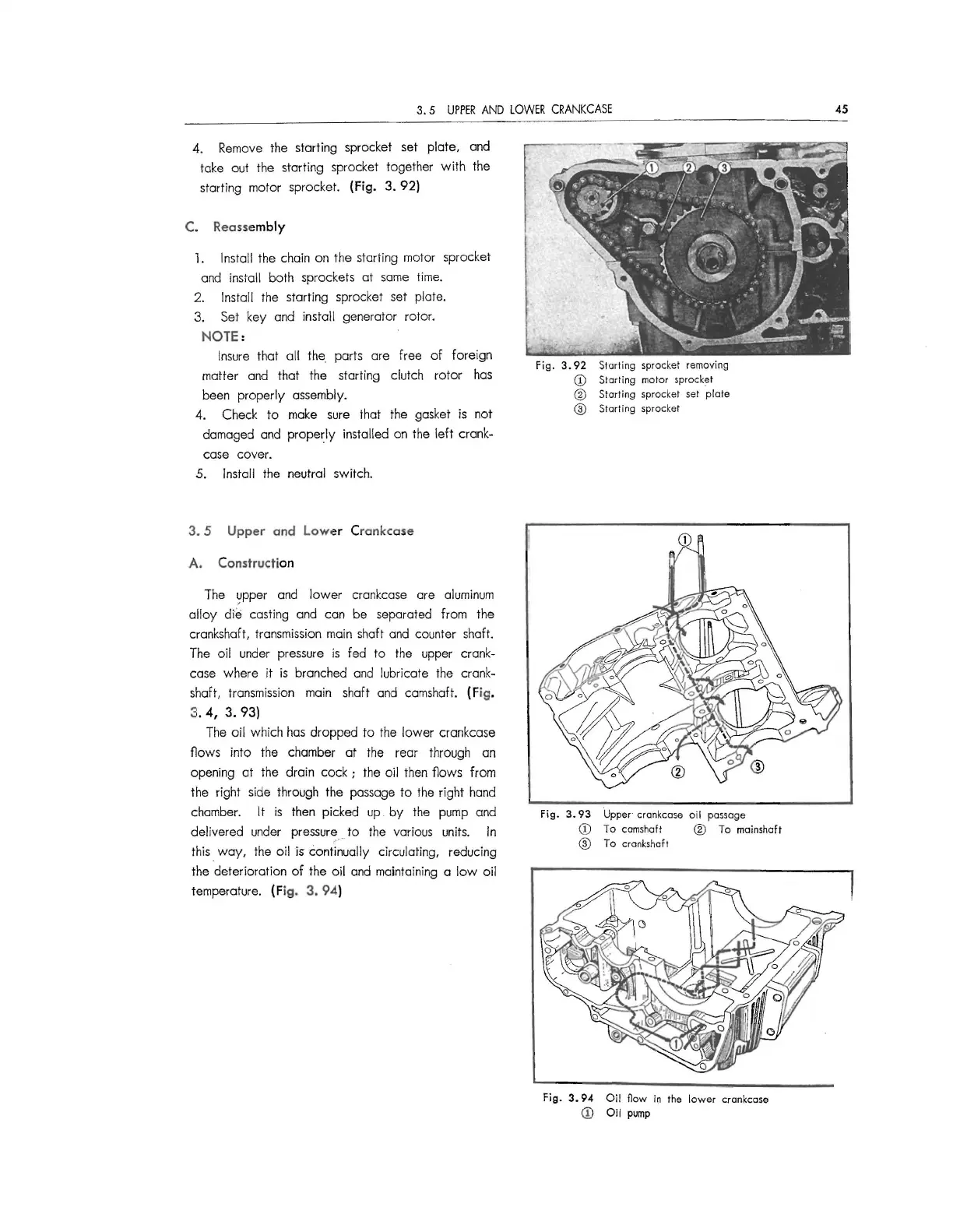
4. Remove the starting sprocket set plate, and
take out the starting sprocket together with the
starting motor sprocket.
(Fig. 3. 92)
C. Reassembly
l. Install the chain on the starting motor sprocket
and install both sprockets at same time.
2. Install the starting sprocket set plate.
3. Set key and install generator rotor.
NOTE:
Insure that all the parts are free of foreign
matter and that the starting clutch rotor has
been properly assembly.
4. Check to make sure that the gasket is not
damaged and properly installed on the left crank-
case cover.
5. Install the neutral switch.
3.
5 Upper and Lower Crankcase
A. Construction
The
~pper and lower crankcase are aluminum
alloy
die costing and con be separated from the
crankshaft, transmission main shaft and counter shaft.
The oil under pressure is fed to the upper crank-
case where it is branched and lubricate the crank-
shaft, transmission main shaft and camshaft.
(Fig.
3. 4, 3. 93)
The oil which hos dropped to the lower crankcase
flows into the chamber at the rear through an
opening at the drain cock
; the oil then flows from
the right side through the passage to the right hand
chamber. It is then picked
up. by the pump and
delivered under pressurE;
.... to the various units. In
this way, the oil is continually circulating, reducing
the deterioration of the oil and maintaining a low oil
temperature.
(Fig. 3. 94)
Fig . 3. 92 Starting sprocket removing
CD Starting motor sprocket
® Starting sprocket set plate
@ Starting sprocket
fig .
3. 93 Upper· crankcase oil passage
CD To camshaft ® To mainshaft
@ To crankshaft
Fig. 3. 94 Oil flaw in the lower crankcase
CD Oil pump
45
 Loading...