A2
3. ENGINE
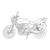
Fig. 3. 82 Sect,onal view of oil pump
CD Plunge, @ Steel ball @ Boll sear
© Ball stopper ® Rubber seat
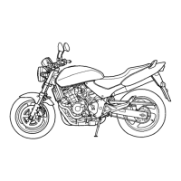
Fig. 3. 83 Oil pump exploded view
CD 32 mm circlip ® Pump rod side washer
@ 8 X 12 Knock pin © 8 X 1. 5 0 ring
® Oil pump boll stopper bolt " ® 17X2. 5 0 ring
Cf> #10 Steel Lall @ Oil pump boll seat
® Rubber ring
@ Rubber seat
@ Pump plunger
@ Oil pump body
@ 6 mm lock wosher·
@) Oil pump boll stopper
@ O il pump plunger pin
@ Pump rod
@ Filter screen
@ 6 X28 hex bolt
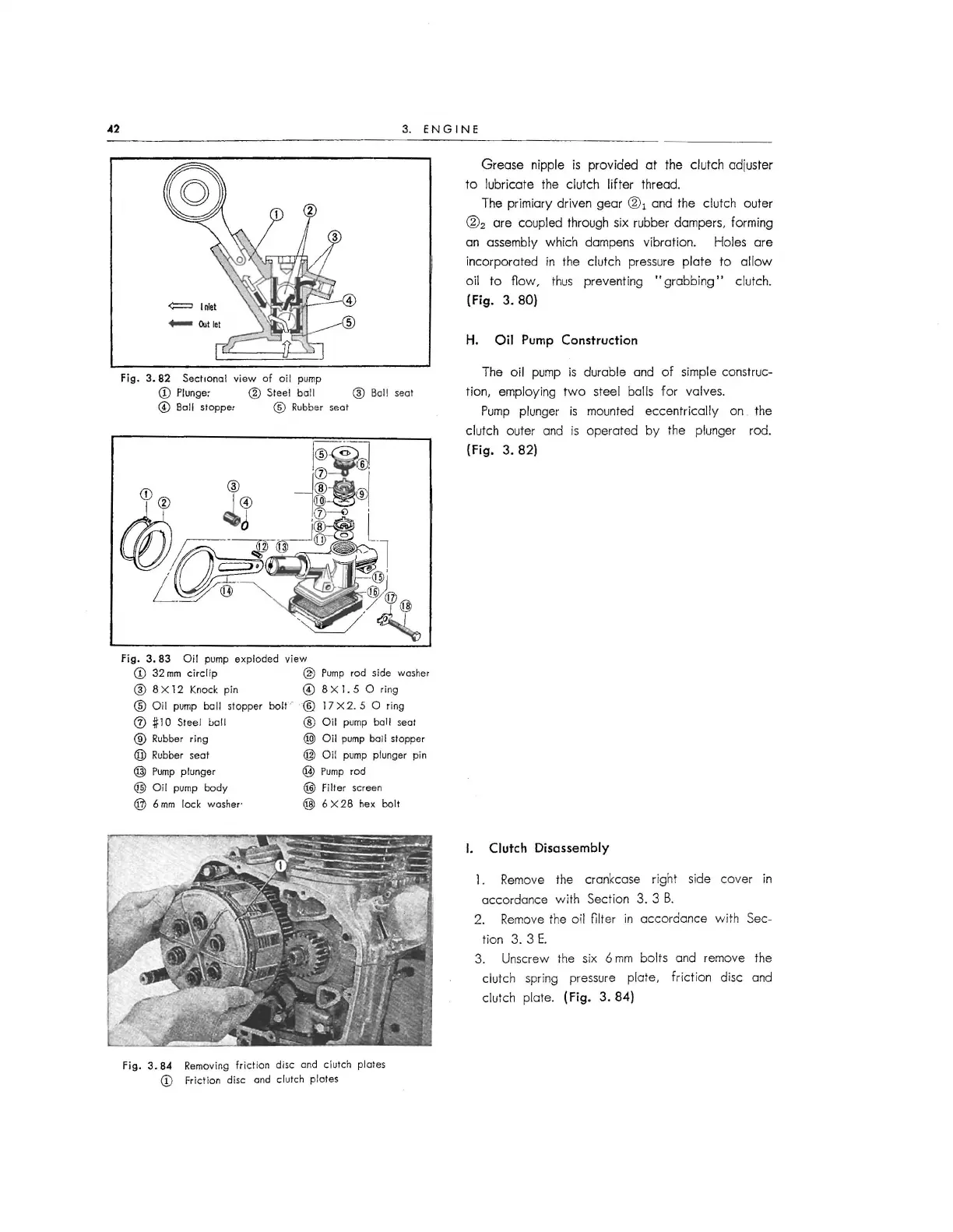
Fig. 3.
84 Removing frict ion disc and clutch plotes
CD Friction disc and clutch plates
Grease nipple is provided at the clutch adjuster
to lubricate the clutch lifter thread.
The primiary driven gear
(]:\ and the clutch outer
@
2
are coupled through six rubber dampers, forming
an assembly which dampens vibration. Holes are
incorporated in the clutch pressure plate to allow
oil to
fiow, thus preventing "grabbing" clutch.
(Fig. 3. 80)
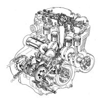
H. Oil Pump Construction
The oil pump is durable and of simple construc-
tion , employing two steel balls for valves.
Pump plunger is mounted eccentrically on the
clutch outer and is operated by the plunger rod.
(Fig. 3. 82)
I. Clutch Disassembly
1. Remove the crankcase right side cover in
accordance w ith Section 3. 3 B.
2. Remove the oil
filter in accordance with Sec-
tion 3. 3 E.
3. Unscrew the six 6 mm bolts and remove the
clutch spring pressure plate, friction disc and
clutch plate .
(Fig. 3. 84)
 Loading...