3. 5 UPPER AND LOWER CRANKCASE 49
t
A
t
B
t
C
t
D
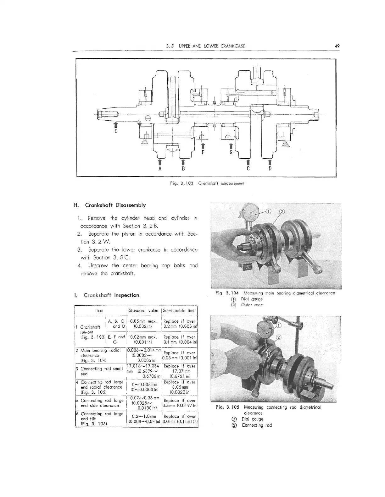
fig. 3. 103 Crankshaft measurement
H. Crankshaft Disassembly
1. Remove the cyl inder head and cylinder in
accord ance with Sect ion 3. 2 B.
2. Separate the piston in accordance with Sec-
tion 3. 2 W.
3. Separate the lower crankcase in accordance
with Sectio n 3. 5
C.
4. Unscrew the center bearing cap bolts and
remove the crankshaft.
I. Crankshaft Inspection
Item I Standard value
[ Serviceable limit
I A, B, C I
0.05m m max,
I .
I Replace ,f over
l
Crankshaft and DI
10.002 inl
I 0.2 mm I0.008 inl
run-out -- -
!Fig. 3. 1 03)\ E,
6
and I
·o.02m m max.
Replace if over
10.001 inl
0.1 mm I0.004 inl
2 Main bearing
radial
I 0.006- 0.0 14 mm
Replace if over
clearance
I0.0002 -
!Fig.
3. 1041
0.0005 inl
0.03 mm 10.001 inl
3
Connecting rod
small
17.016-17.034 Replace if over
end
mm I0.6699- 17.07 mm
I
0.6706
inll 10.6721 inl
4
Connecting rod large
I
O-O.OOB mm , Replace if over
end radia l clearance
I0-0.00 03 inl IOoig
2
~~nl
!Fig. 3.
1051
I
0.07-0.33 mm
Replace if over
5 Connecting rod large
I
(0.0028-
end side clear ance
0.0130 inl
0.5 mm IO.O 197 in}
6 Connecting rod large
I
O 2
1 0
R
1
·f
d flt . - . mm ep ace I over
fF~g. ~- 106) l0,008-0 .04 inl 3.0 mm 10.1181 inl
Fig .
3. 104 Measuring main bearing diametrical clearance
CD Dial gouge
® Outer race
Fig. 3. 105 Measuring connecting rod diametric:al
clearance
CD Dial gauge
@ Connecting rod
 Loading...