3. 2 CYLINDER HEAD
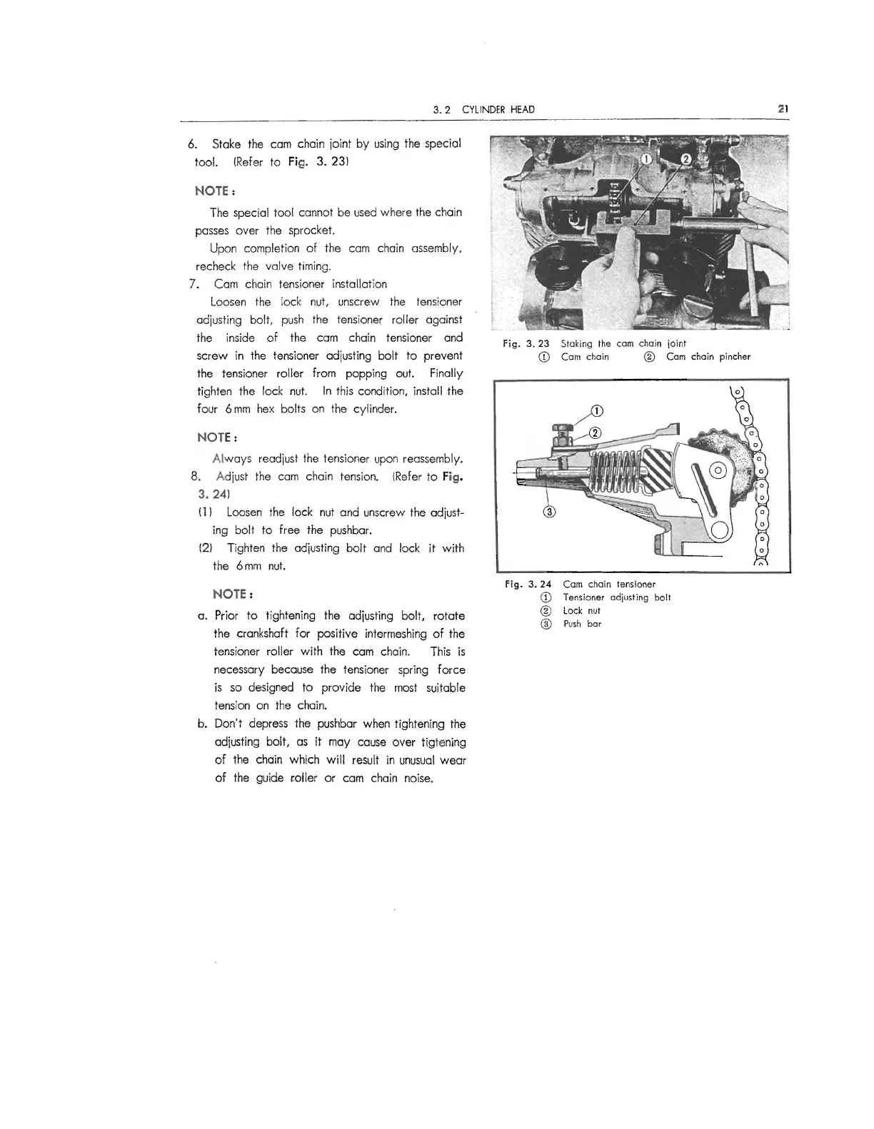
6. Stake the cam chain joint by using the special
tool. (Refer to
Fig. 3. 23)
NOTE:
The special tool cannot be used where the chain
passes over the sprocket.
Upon completion of the cam chain assembly,
recheck the valve timing.
7. Cam chain tensioner installation
Loosen the lock nut, unscrew the tensioner
adjusting bolt, push the tensioner roller against
the inside of the cam chain tensioner and
screw in the tensioner adjusting bolt to prevent
the tensioner roller from popping out. Finally
tighten the lock nut. In this condition, install the
four 6 mm hex bolts on the cylinder.
NOTE:
Always readjust the tensioner upon reassembly.
8. Adjust the cam chain tension. (Refer to
Fig.
3. 24)
( l l Loosen the lock nut and unscrew the adjust-
ing bolt to free the pushbar.
(2) Tighten the adjusting bolt and lock it with
the 6mm nut.
NOTE:
a. Prior to tightening the adjusting bolt, rotate
the crankshaft for positive intermeshing of the
tensioner roller with the cam chain.
This is
necessary because the tensioner spring force
is so designed to provide the most suitable
tension on the chain.
b. Don't depress the pushbar when tightening the
adjusting bolt, as it may cause over tigtening
of the chain which will result in unusual wear
of the guide
roller or cam chain noise.
Fig . 3. 23 Staking the cam chain joint
© Cam chain ® Cam chain pincher
Fig.
3. 24 Com chain tensioner
© Tensioner adjusting bolt
® Lock nut
@ Push bar
:21
 Loading...