EasyManua.ls Logo

Honeywell Home VNT5200H1000 User Manual

Honeywell Home VNT5200H1000
88 pages
To Next Page IconTo Next Page
Page #1 background imageLoading...
Page #1 background image
Tools required to install ERV/HRV
Aluminum foil tape (UL181B)
Standard screwdriver
Crescent wrench
Hex driver (1/4 in.)
Accessories (not included)
6 in. Dia. insulated duct (VNT5150, VNT5200,
VNT6150 & VNT6200)
6 in. Dia. duct (VNT5150, VNT5200)
Two 6 in. Dia. weather hoods (VNT5150, VNT5200 ,
VNT6150 & VNT6200)
5in.Dia.insulatedexduct(VNT5070)
5in.Dia.exduct(VNT5070)
6in.Dia.matrixhood,50063805-009(VNT5070)*
* 6 in. to 5 in. reducer required
D1
A3
E
A1 A2 B C
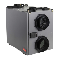
ERV/HRV VNT5150H1000, VNT5150E1000 or
VNT6150H1000
ERV/HRV VNT5200H1000, VNT5200E1000 or
VNT6200H1000
ERV/HRVVNT5070H1000orVNT5070E1000
Heat/Energy Recovery Core (1)
Filter (2)
Round Duct Collars (4) (VNT5150 and VNT5200,
VNT6150 & VNT6200)
OvalDuctCollars(VNT5070)
Installation Kit (flex included with 5150 and 5200,
VNT6150 & VNT6200)
WallMountBracket(VNT5070)
Optional Controls: 1 - Prestige IAQ Kit, 2 - True IAQ,
3 - Dehumidistat H8908D, 4 - Prestige IAQ,
5 - 20/40/60 Minute Boost Control,
6 - W8150 Ventilation Control
7 - Vent Boost Remote, 8 - VisionPRO Wi-Fi
A1
E
F
D1
D2
A2
A3
B
C
G
F
D2
OPTIONAL CONTROLS SOLD SEPARATELY
G8
G3
G6 G7
G5
G4
G1 G2
PROFESSIONAL INSTALLATION GUIDE.
GUIDE D’INSTALLATION PROFESSIONNELLE.
69-2480EF-17
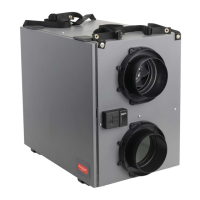
TrueFRESH™ ERV/HRV Ventilation Systems
Systèmes de ventilation V/VRC TrueFRESH
INCLUDED IN THIS BOX

Questions and Answers:

Honeywell Home VNT5200H1000 Specifications

General IconGeneral
Model NumberVNT5200H1000
Voltage120V
Airflow5200 CFM
Airflow Capacity5200 CFM
Power SourceAC
Motor TypeAC

Summary

Installation Considerations

System Integration & Compatibility

Ensures proper operation when integrated with other mechanical systems.

About the ERV/HRV Ventilation System

Critical Safety Warnings

Essential safety precautions for installation, operation, and servicing to prevent injury or damage.

Determining Ventilation Needs

ASHRAE 62.2 Sizing Standards

Ventilation requirements based on floor area and number of bedrooms per ASHRAE 62.2.

Ventilation Performance Data

VNT5150H1000 Performance Metrics

Airflow and energy performance data for the VNT5150H1000 model.

VNT5200H1000 Performance Metrics

Airflow and energy performance data for the VNT5200H1000 model.

VNT5150E1000 Performance Metrics

Airflow and energy performance data for the VNT5150E1000 model.

VNT5200E1000 Performance Metrics

Airflow and energy performance data for the VNT5200E1000 model.

VNT5070H1000 Performance Metrics

Airflow and energy performance data for the VNT5070H1000 model.

VNT5070E1000 Performance Metrics

Airflow and energy performance data for the VNT5070E1000 model.

VNT6150H1000 Performance Metrics

Airflow and energy performance data for the VNT6150H1000 model.

VNT6200H1000 Performance Metrics

Airflow and energy performance data for the VNT6200H1000 model.

Installation Application Types

Independent System Installation

Illustrates a standalone ERV/HRV system configuration.

Installation Application Types (continued)

Exhaust at Source, Supply in Return

ERV/HRV connected to a forced air system's return duct for distribution.

Exhaust and Supply in Return Configuration

ERV/HRV fresh air and exhaust ducted into the return air duct.

Installation Steps

Selecting the Installation Area

Guidance on choosing a suitable, conditioned location for unit installation.

Installation Steps (continued)

Installing Flexible Ductwork

Detailed steps for connecting flexible ducting to unit collars for noise dampening.

Condensation Drain Line Installation

Procedures for installing the drain line or setting up a drainless application.

Power Cord Connection and Safety

Steps for connecting the power cord and essential electrical safety notes.

Wiring and Terminal Connections

Terminal Block Description

Identifies and describes the terminals on the unit's wiring block.

Wiring Diagrams

Remote Control Wiring Configurations

Wiring for CONT/INT modes with remote controls and Prestige IAQ/RF EIM.

Control Panel Functionality

Control Panel Overview and LED Indicator

Description of the control panel's selector switch, speed buttons, and LED indicator.

Speed Control as Mode Selector

How the selector switch operates as INTER, CONT, or OFF modes.

Speed Control for Balancing Motors

Using the selector switch to control exhaust, fresh, or both motors for balancing.

Balancing Procedures

Entering Balancing Mode

Steps to activate balancing mode using simultaneous button presses.

Airflow Measurement and Adjustment

Procedures for measuring and adjusting airflow in fresh and exhaust ducts.

Exiting Balancing Mode

Steps to exit balancing mode and return the unit to normal operation.

Balancing Reset and Checkout

VNT5070 Airflow Measurements

VNT5070 Airflow Measurements (continued)

Cleaning Procedures

Troubleshooting Common Issues

No Power or Green LED Faults

Diagnosing and resolving issues related to unit power and speed control LED.

Troubleshooting Common Issues (continued)

Related product manuals