4 - 24
MAN0443.P65 Issue 13 Aug 04 5701 Control System
05701-M-5001 A02279
CHAPTER 4 - INSTALLATION INSTRUCTIONS
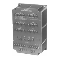
be accommodated. A link is closed by fitting the jumper provided so that
the two pins of the link are connected. Unused links should have their
jumper removed from the Sensor Drive Module altogether or carefully
fitted over a single pin of an unused link as follows:
Sensor Drive Module Open, Closed and Spare Link
Arrangements
The closed link positions required for the most common sensor
configurations are given in Section 13.3.
LK13
LK1
05701-A-0283
Open
Spare
Shorted

 Loading...