BENDIX/KING RDR 2000
Page 2-14 00643I05.TDC Rev 7, July/2002
2.4.3.3 Equipment Configuration Procedure
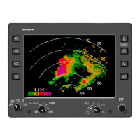
The buttons referred to in the following procedure are located on the radar control panel or radar
indicator.
A. Press the Wx button until the MAINT FUNCTIONS menu is again displayed. See figure 2-
8A.
B. Press the GND MAP button to move the select pointer on the display to EQUIPMENT
CONFIG.
C. Press the WxA button to display the EQUIP CONFIG menu. See figure 2-8B.
D. Press the GND MAP button to move the select pointer on the display to ANTENNA CON-
FIG.
E. Press the WxA button to display the ANTENNA CONFIG options. See figure 2-8C.
F. Press the GND MAP button to select each displayed option. Press the WxA button to se-
lect the desired setting in the bracket of the selected option. Set each option to the condi-
tion that satisfies the installation.
G. Press the Wx button until the EQUIP CONFIG menu is again displayed. See figure 2-8D.
H. Press the GND MAP button to move the select pointer on the display to CONTROLLER
CONFIG.
I. Press the WxA button to display the CONTROLLER CONFIG options. See figure 2-8E.
J. Press the GND MAP button to select each displayed option. Press the WxA button to se-
lect the desired setting in the bracket of the selected option. Set each option to the condi-
tion that satisfies the installation.
K. Press the Wx button until the EQUIP CONFIG menu is again displayed. See figure 2-8F.
L. Press the GND MAP button to move the select pointer on the display to SENSOR CON-
FIG.
M. Press the WxA button to display the SENSOR CONFIG options. See figure 2-8G.
N. Press the GND MAP button to select each displayed option. Press the WxA button to se-
lect T (true) or F (false) in the bracket of the first three selected options. The REF LEVEL
must set to the proper gyro reference voltage level which corresponds to the gyro installed
in the aircraft.
Select NONE
for no analog input, 26 V for a 26 V input, 115 V for a 115 V input, and 10 V for
all other voltage ranges. Set each option to the condition that satisfies the installation.