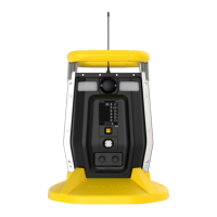
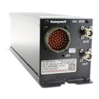
IS barrier parameters:
Input Rated 110~230VAC/50~60Hz
Consumption ≤ 3W
Output (to hazardous area) Uo=23.5V;
Io=150mA;
Po=1.15W;
Co=132nF;
Lo=1.5mH
Operating Temp. -20 to 60 ℃
Relative humidity 5 to 95% without condensing
Installation In safe area
Extension cable (W03-2168-000)
W03-2168-000 IS barrier to BW RigRat cable, 100meters, with 3-pin connector.
Total 100m cable IS parameters: (C=80pF/m; L=0.7uH/m; R=23.2mΩ/m)
Ct=8nF
Lt=0.07mH
BW RigRat IS parameters in hazardous area:
Ui=24V
Ii= 150 mA
Pi=1.15W
Ci=0.36nF.
Li=0uH
For hazardous applications, these conditions must be met:
Uo ≤ Ui
Io ≤ Ii
Po ≤ Pi
Co ≥ Ci + Ct
Lo ≥ Li + Lt
Uo/Io/Po/Co/Lo are IS barrier output parameters
Ui/Ii/Pi/Ci/Li are RigRat input parameters
Ct/Lt are extension cable additional parameters

 Loading...


