22 107062-12 EN FR26 GLO 501 Printed in France
Indicators
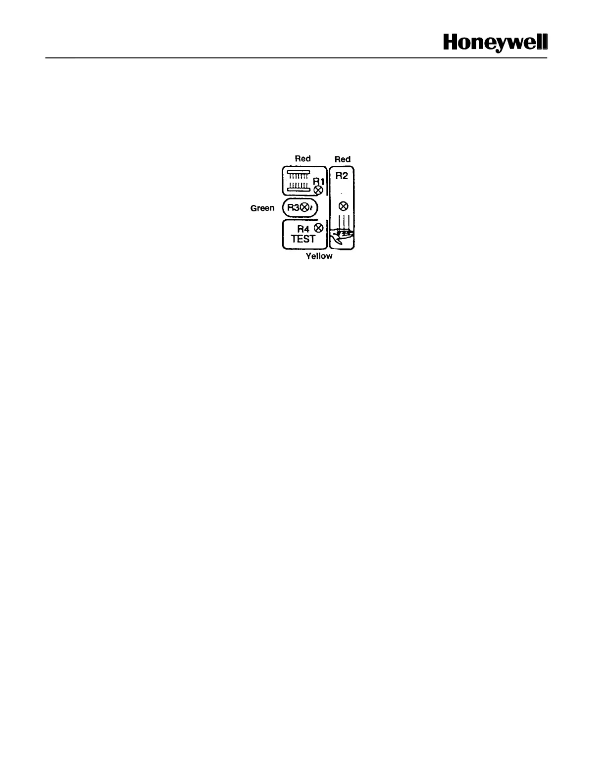
FF-SB12, FF-SB14 and FF-SB15 Series receivers have four LED indicators (see figure 1-8). The emitters
have one LED. These LED indicators provide important information related to light curtain status.
Figure 1-8 Receiver Indicators
Signal Strength Indicator (receiver)
The R1 indicator will flash repeatedly if the received light level is lower than the normal operating level, but is
still sufficient for operation. If the received light level drops too low, an alarm state results and the light curtain
generates a stop signal. To prevent unnecessary shutdowns, this indicator will signal the need for cleaning
and/or alignment.
Operation Indicators (receiver)
There are two LED indicators that provide operation status (see figure 1-8): R2 (red) and R3 (green). R3
indicates the receiver is operating normally and the sensing field is clear. This indicator must be on to ensure
the equipment is working properly (red R2 will be off).
R2 indicates that the light curtain is in an alarm state. If the sensing field is interrupted, the FF-SB Series light
curtain will immediately generate a stop signal. In this condition, R2 will be on and R3 will be off.
Test Indicator (receiver)
FF-SB Series light curtains provide a connection for testing the state of external contacts. The test contacts
allow verification of external safety-related electromechanical components. When any contact in the external
test circuit opens, the FF-SB Series light curtains will switch to the alarm state. R4, the test indicator, will turn
on and the relay outputs will be de-energized while the test circuit is open.
The customer is responsible for providing the external test circuitry. See figures 3-3, 3-4 and 3-5 for the
wiring diagrams of the external test circuitry.
 Loading...


