107062-12 EN FR26 GLO 501 Printed in France 53
Cycle Start Mode
During the cycle start mode, the R4 LED on the receiver flickers and the cycle start mode push-button on the
external relay monitoring loop (C3-C5) requires actuation. Once actuated, the light curtain changes to a
green condition (R3 LED is illuminated, R2 LED is not illuminated) and allows the machinery to operate.
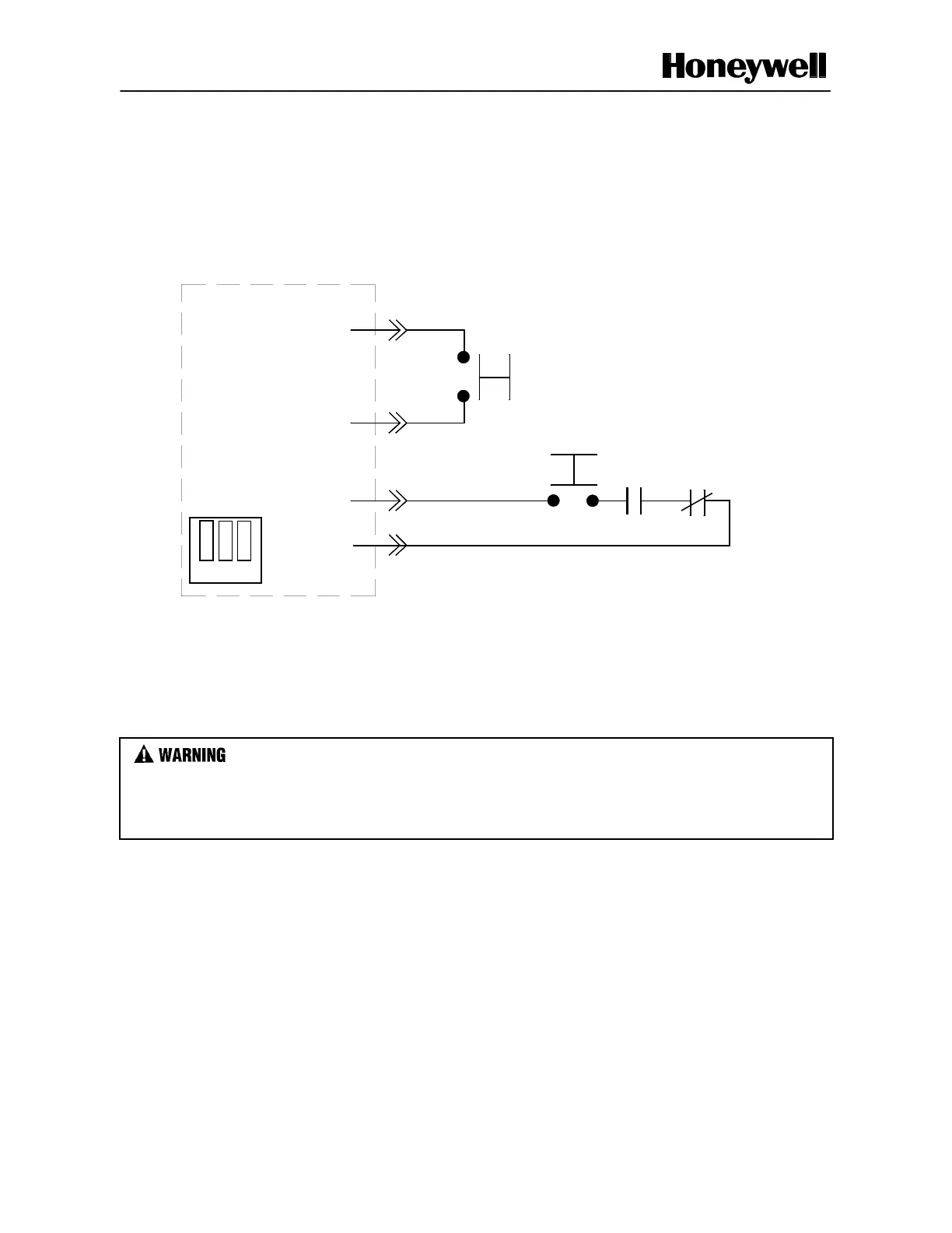
Figure 3-5 FF-SB Series CE Version (cycle start mode) with external relay monitoring by the FF-SB
NOTICE: Points C4 and B3 are jumpered
if the optional test function is not used
(no voltage is applied).
C5
C3
B3
RECEIVER
C4
Optional test function
R2
R1
Cycle start mode
● ● ●
● ● ●
● ● ●
Wiring Diagrams
IMPROPER SYSTEM PERFORMANCE
Ensure independent stop circuit safety relays have mechanically linked contacts that prevent contact
overlapping in the event of a welded contact.
Failure to comply with these instructions could result in death or serious injury.
The following wiring diagrams illustrate the electrical connections for the FF-SB Series light curtains. The
customer must supply the three safety relays, R1, R2 and R3, the cycle start push-button and the test circuit.
Mechanically linked contact relays are sometimes called captive contact, anti-weld, or guided contact relays.
Jumper links on the receiver
power board provide access
to this mode
 Loading...


