107062-12 EN FR26 GLO 501 Printed in France 51
The wire gauge of the ground connection should be equal to the power supply wire gauge. The length of the
ground connection wire should be as short as possible. To minimize noise interference, the ground terminal
of the light curtain must be connected to the main ground of the machine.
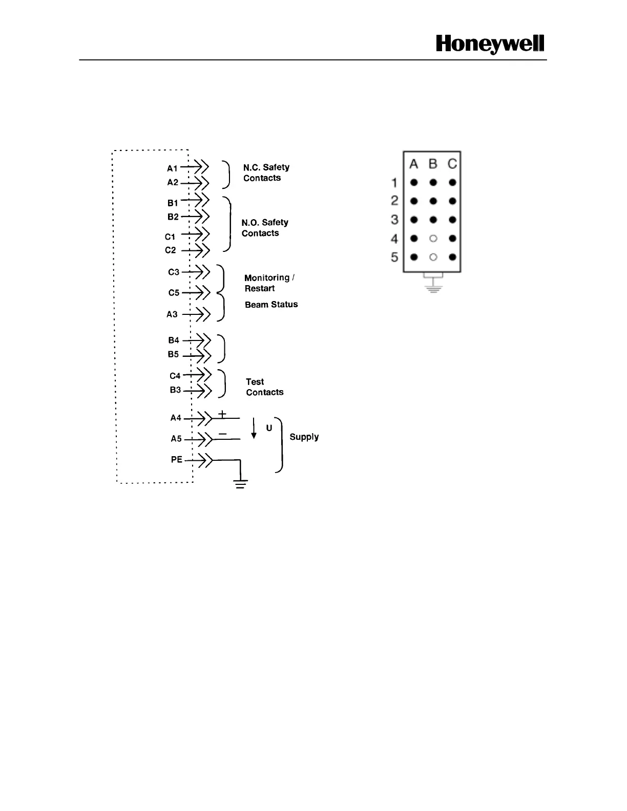
Figure 3-3 Connections for Receivers
Not
Connected
A1, A2: 1 Normally Closed (NC) safety contact
B1, B2 and C1, C2: 2 Normally Open (NO) safety contacts
A3, C5: Beam status, A3 is internally connected to the 0 V when the beams are unobstructed (NPN output),
I = 5 mA to 20 mA, 30 Vdc max.
C3, C5: Restarts the safety light curtain and monitors the external relays.
Receiver
Connector Pinout
Earth Ground
Earth Ground
 Loading...


