107062-12 EN FR26 GLO 501 Printed in France 63
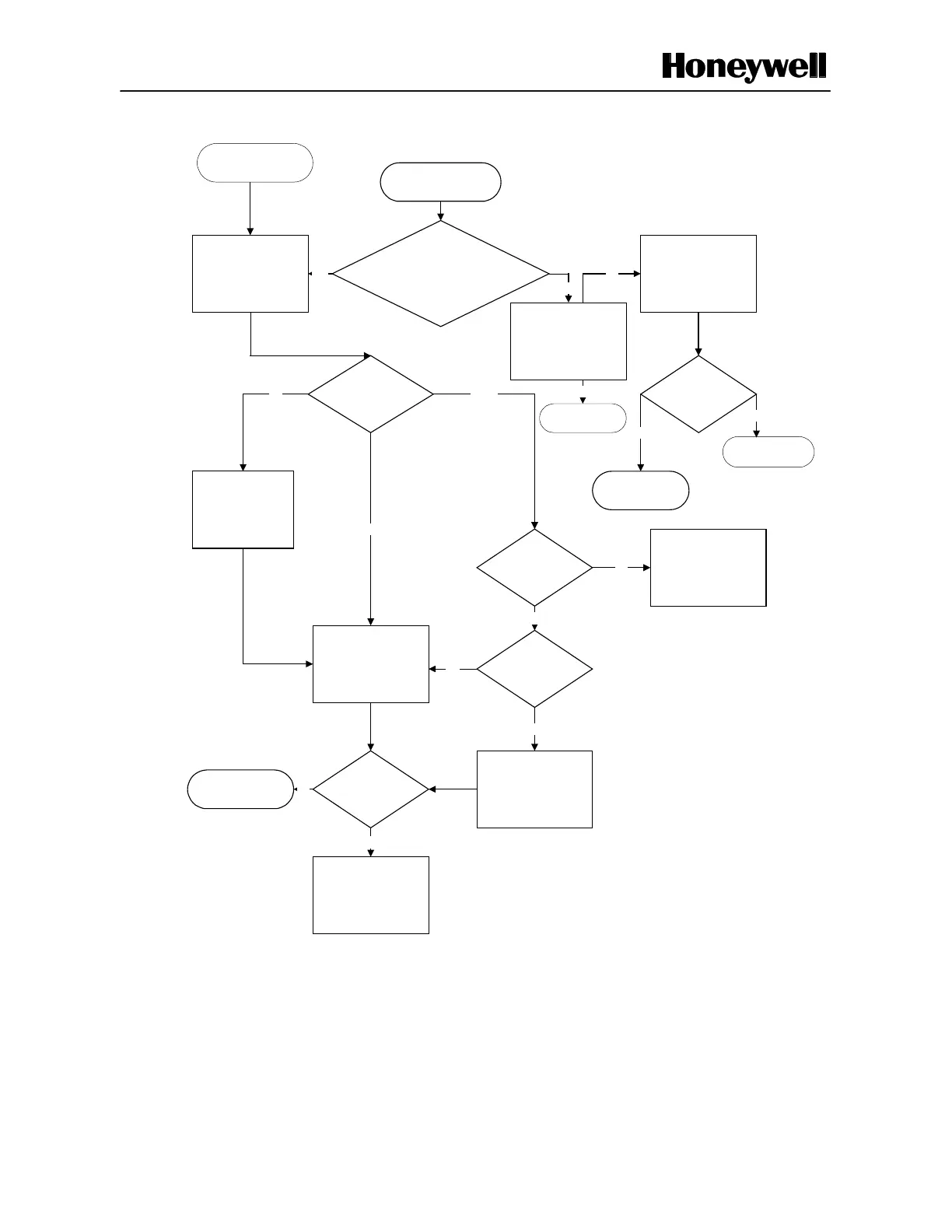
Figure 4-3 Troubleshooting Flow Diagram (Sheet 2 of 2)
Continued from Sheet 1
When the sensing field is clear
and the emitter and receiver are
correctly aligned; Check if E1
and E2 LEDs on the emitter are
illuminated. Ensure the front
plate is clean.
Check Status of LED R4
Emitter Failed, Replace with
Alternate One
Problem Resolved?
Yes
Machine Working
On Flicker
Off
Faulty Receiver Power
Supply Board
Correct Supply
Voltage?
Correct Supply VoltageNo
Check Receiver Mode
Setting
Yes
Replace Receiver
OK
Problem Resolved?
Machine Works
Yes
Correct Mode Settings
No
Return emitter and
receiver to Honeywell
No
Check Receiver
(ensure alignment is correct;
ensure front window is clean)
Yes
Process
Visually check all the red
light spots on the emitter are
No
***
No
Go to ***
Yes
Go to ***
No
illuminated.
 Loading...


