66 107062-12 EN FR26 GLO 501 Printed in France
Repair and Maintenance
This section provides step-by-step instructions related to repair and maintenance..
The tools required include a Philips head screw driver and a #20 Torx driver.
WARRANTY CONDITIONS
Repair and maintenance are limited only to : power supply module replacement, optical controller module
replacement, and fuse replacement.
Please send back the board to Honeywell for repair.
Failure to comply with these instructions could result in death or serious injury.
Interchangeability
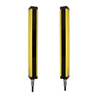
Emitter and receiver units are not matched. An emitter unit from one FF-SB system may be used with the
receiver unit from another if the catalog listings of the units are the same. If a replacement for one part of a
FF-SB system is required, maintenance time is greatly reduced.

 Loading...
