Installation Guide and Operating Manual
Honeywell 18
3.3 LED Status Indicators
The Model FS24X Detector uses three (3) separate, bright LED’s to indicate the Detector’s status.
The Green LED blinks (flashes) once every ten (10) seconds to indicate a Normal, safe operational
condition (i.e. no Faults and no Alarms). The Green LED is OFF when no external 24 VDC input power is
applied to the Detector.
The Red LED turns ON when a fire is Alarmed.
The Yellow LED blinks (flashes) when the window lens is dirty. For all other Fault conditions, the Yellow
LED will turn ON.
3.4 Normal Operation
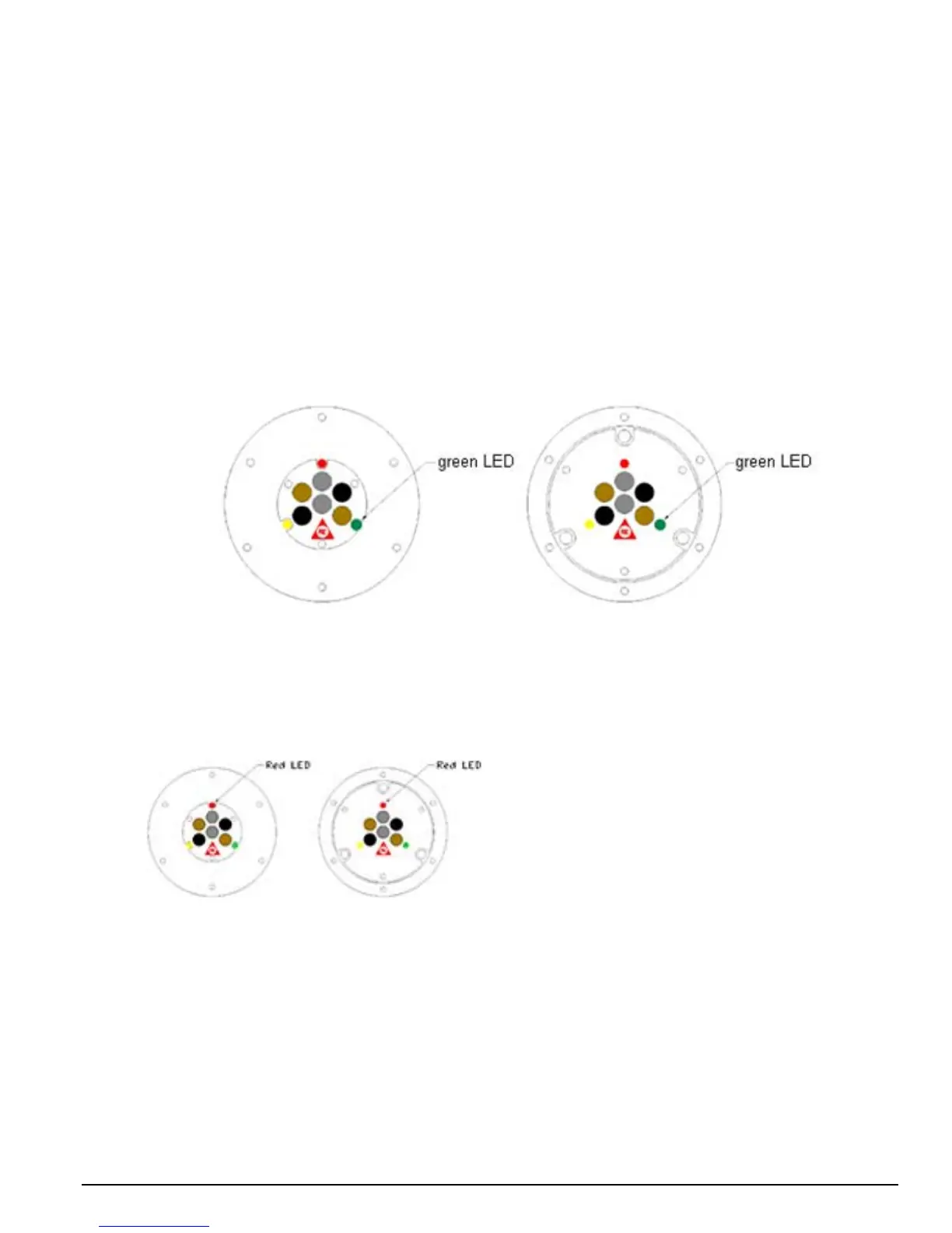
In Normal operation, the bright Green LED blinks (flashes) every 10 seconds. See Figure 3-4 for the
location of the Green LED. Normal Operation is defined as the Detector with 24 VDC applied and no Alarm
or Fault conditions are present. If one of the 4-20 mA options are selected (Table 3-1), the current, sink or
source, will be 4.0 mA (±0.6 mA). Only the current source mode has been certified to the EN54-10 standard.
Figure 3-4
Green LED Location
3.5 Alarm Condition
When an Alarm condition occurs, the Red LED will turn ON, (factory setting with the Auxiliary relay set to “0”
seconds). See Figure 3-5 for the location of the Red LED.
The Detector has the following outputs with
an Alarm condition:
Alarm Relay activation
Auxiliary Relay activation
1
4-20 mA (sink 20 mA) Output
2
4-20 mA (source 20 mA) Output
2
RS-485 FireBus
II Alarm Notification
2
RS-485 Modbus Alarm Notification
2
1 This output is a Verified Alarm Output
2 Only one active Alarm output from this group
Figure 3-5
Red LED Location

 Loading...


