Installation Guide and Operating Manual
Honeywell 14
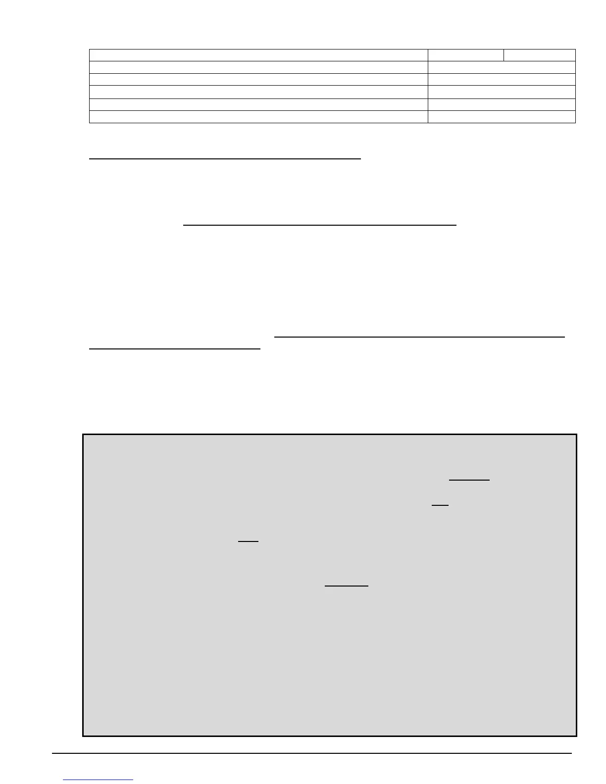
Auxiliary Relay Verify Time is set to 5 seconds
SW2-4 ON SW2-5 ON
End of Line Resistor is Disabled
SW2-6 OFF
Fault Relay Output is Normally Energized
SW2-8 ON
Communication is set to FireBusII™
SW3 is set to Position 4
Factory Use Only
SW1-1 through SW1-3 OFF
Digital Communication Address is set to 127
SW1-4 through SW1-10 ON
If the application for the Detector requires different settings, refer to Section 3.2 for detailed descriptions.
U
Before applying 24 VDC power to the Detector, make sure
U:
1. Wire connections are correct (Section 2.3). Each wire must be stripped properly to the correct length,
loose wire strands must be removed and each wire must be securely and firmly screwed clockwise in
the connector.
2. If using conduit, ensure a proper conduit seal, (appropriate for the area classification), has been
installed and
Uall measures to prevent moisture ingress have been takenU.
3. Consult the manufacturer for dimensional information on the flameproof joint specifications.
4. The FSX Detector is securely mounted and has an unobstructed view of the area of coverage
(Section 2.1).
5. The Detector window is unobstructed and clean.
6. To ensure optimum performance, shield the detector face from intense bright light sources when first
energized.
The Detector is now ready for Power-Up.
Uon Power-Up, the Fault Relay will change status if the Factory
Default Setting is used (Section 3.2).
2.5 Start-Up and Commissioning
During Start-Up and Commissioning, DISABLE all outputs from the Detector to any control panels or control
devices. As with any flame and fire detector, after the Detector(s) is powered, perform an external Detector
test “end to end”. Using an external hand-held test lamp ensures that the Detector has a clear unobstructed
view of the threat area and the wiring is correct to the control panel or device.
Note: Honeywell Analytics FSX Detectors feature an automatic built-in “through the lens” test that
verifies the cleanliness of its viewing window lens and test its internal electronics and
software. As with any any optical fire and flame detector, this does not constitute a fully
functional “end to end” test as these types of internal self-tests only Upartially Ucheck and test
the operational readiness of a detector.
In order to test the full functionality and operational readiness of UanyU fire or flame detector
“end to end”, without starting a real fire (which is not permitted in hazardous areas), it is
necessary to test the detector(s) with an external test lamp.
Using a test lamp is the UonlyU non-hazardous and safe method to test any flame or fire
detector’s sensors, internal electronics and its alarm activation software, viewing window
lens cleanliness, terminal wiring integrity, actual relay activation, and the proper functionality
of any other outputs that are used. Also, since most detectors are installed in a fire alarm
system, this is the only method to test the complete fire alarm system, ensuring all the system
wiring and cabling and system control panel are properly installed.
Additionally, using an external test lamp eliminates the following detector conditions:
1. The fire or flame detector(s)’ window lens being covered up (such as paint, paint over
spray, paint masking material, hanging garments, etc.),
2. Improperly positioned and oriented for coverage of the threat area,
3. Partial or full blockage of the detector’s line of sight by one or more objects (i.e., recently
installed air ducts or pipes, storage boxes, vehicles, etc.) such that the threat area is not
fully protected. Since all optical fire and flame detectors are line-of-sight sensors, they
must be properly positioned and oriented with an unobstructed view of the threat area so
that they can detect flames/fires.
To test the full functionality of a FSX Detector, use the Model TL-1055 or TL-2055 Test Lamp in
the manner prescribed in this Instruction Manual.

 Loading...


