Installation Guide and Operating Manual
Honeywell 4
SECTION 1: INTRODUCTION
1.1 Product Overview
The Model FS24X™ Detectors sense the WideBand IR™
radiant energy of blackbody particulate and molecular
emissions generated by BOTH hydrocarbon and non-
hydrocarbon flames and fires. The WideBand IR spectral
radiant energy wavelengths sensed by the Quad (4) sensors
span from approximately 0.4 to 5.5 microns for the FS24X.
The Model FS24X Multi-Spectrum Fire and Flame Detectors
are designed and Factory Mutual approved for use in Class
I,
Div. 1 and 2, Class
II and Class III; Class I, Zone 1 AEx d
and Ex d IIC Hazardous Locations and ATEX Certified Ex db
IIC (T4-T6) and Ex tb IIIC (T4-T6) Flameproof (Figure 1-1 &
Figure 1-2).
The FS24X Detectors are available in copper-free Aluminum
or 316 Stainless Steel enclosure. The FS24X Detector
electro-optical electronics module (puck) is enclosed in a
field-replaceable black, hard anodized aluminum puck that
provides superior ruggedness, handling, ease of installation,
and protection against EMI/RFI.
Figure 1-1
FS24X Detector (
110° Field of View)
Shown with 316 Stainless Steel Housing
FS24X Detector Field Connectors
The field connections feature two (2) connector choices
for the installer:
1. A removable ten (10) pin screw terminal connector
(J2) for hard-wired relay applications.
2. A removable six (6) pin screw terminal connector
(J1) for analog output or RS-485 Digital
Communication applications.
The removable connectors provide quicker installation
and allows the Detector enclosure to be installed prior to
the Detector Module (puck).
Figure 1-2
FS24X-9 Detector (
90° Field of View)
Shown with Copper Free Aluminum Housing
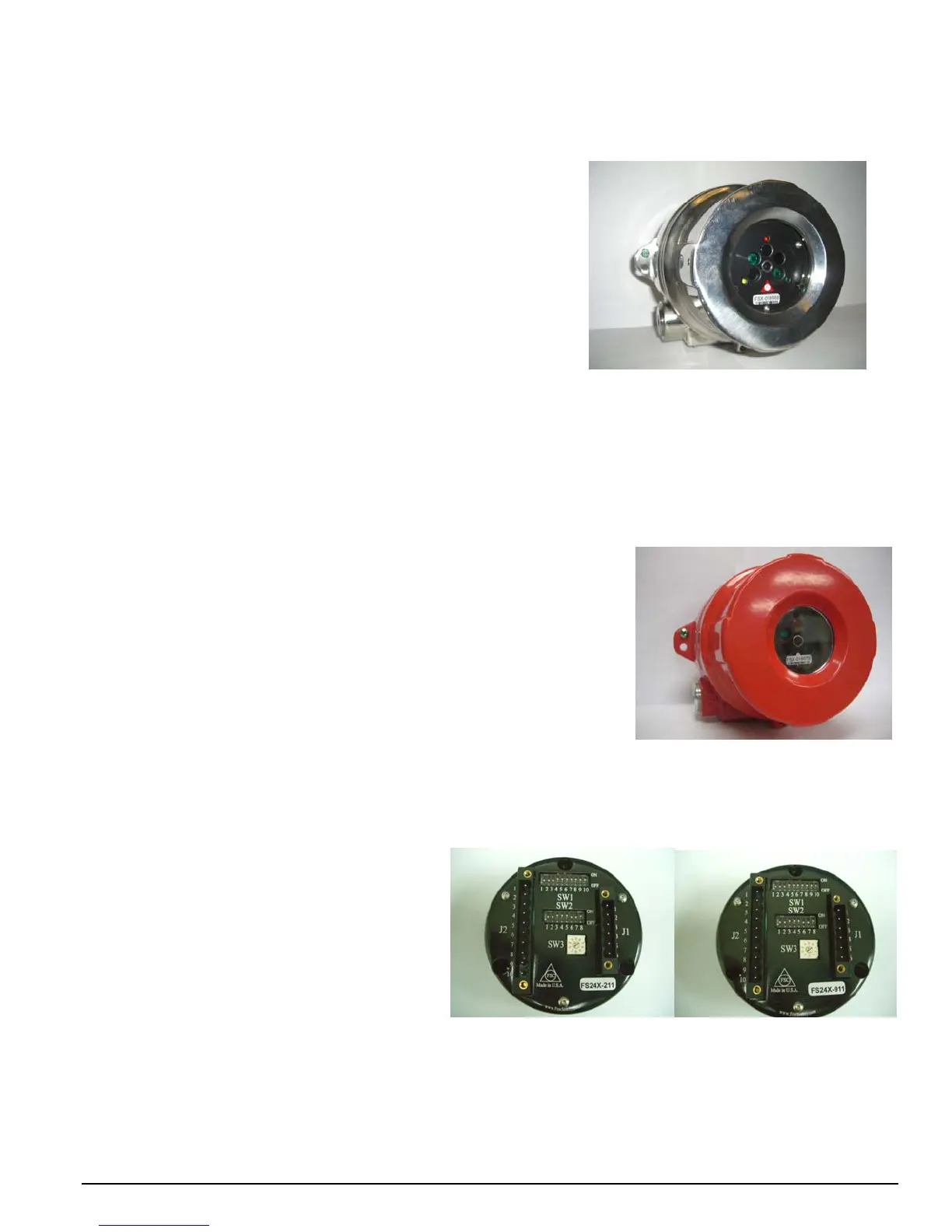
UField Selectable
Configuration Switches
1. The eight (8) pin DIP switch (SW2)
is used to select the Detector’s
Sensitivity and Relay Options.
2. The ten (10) pin DIP switch (SW1)
is used for:
Selecting a unique digital
address (128 choices).
Factory Use
3. The ten (10) position Rotary switch
allows selection of the analog and
digital communication protocol.
Figure 1-3
FS24X and FS24X-9 Detector Puck, (
rear view)

 Loading...


